Interface Specifications ▀
ASR 5000 Installation Guide ▄
Interface Specifications
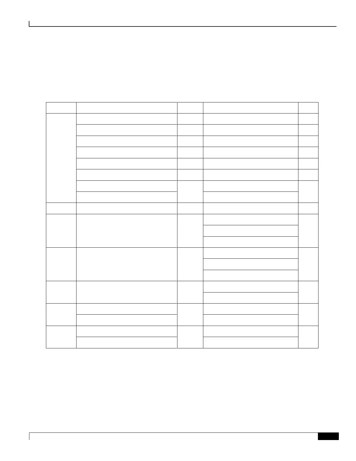
The table below lists the line card interfaces for use within the chassis.
Table 88. Line Card Interfaces
Dual 10-pin Molex to barrier terminal
Single-mode Fiber, LC duplex
Multi-mode Fiber, LC duplex
Channelized (STM-1/OC-3) SM IR-1
Single-mode Fiber, LC duplex
Channelized (STM-1/OC-3)Multi-Mode
Multi-mode Fiber, LC duplex
Notes
1. An RJ-45 Ethernet interface may have more than one pin-out configuration, depending on the type of cable used.
2. An SPIO may be equipped with one type of BITS connector – BNC or 3-pin.
3. A Small Form-factor Pluggable transceiver is supplied with the GLC2 based on the customer-specified interface
type.
4. Four Small Form-factor Pluggable transceivers are supplied with the QGLC based on the customer-specified
interface type.
5. An enhanced SFP (SFP+) transceiver is supplied with the XGLC based on the customer-specified interface type.

 Loading...


