Installation Procedure Overview
▄ ASR 5000 Installation Guide
Chassis Components
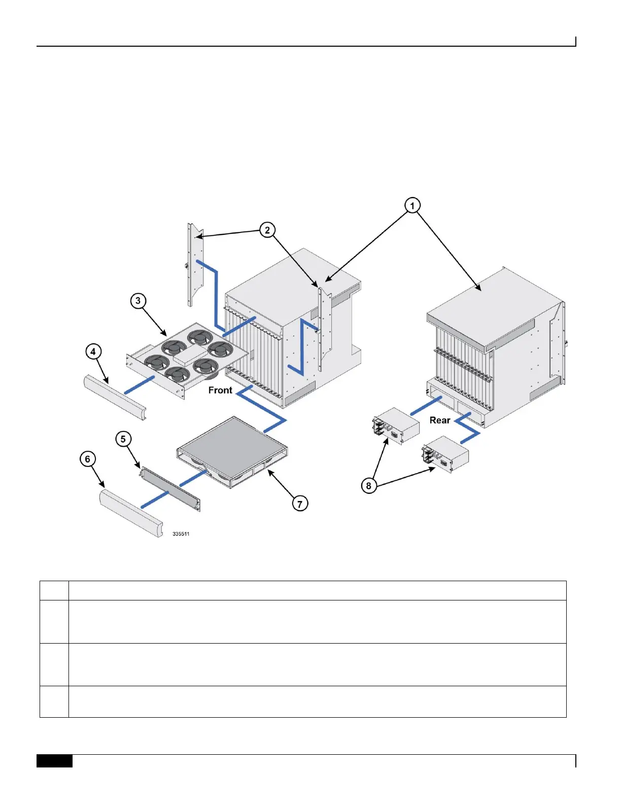
The following graphic and table illustrate the chassis and describe its subcomponents:
Figure 21. ASR 5000 Chassis and Sub-components
Table 23. Chassis and Sub-component Identification Key
Chassis: Supports 16 front-loading slots for application cards and 32 rear-loading slots for line cards. The chassis ships
with blanking panels over every slot except the following: 1, 8, 17, and 24. These are intentionally left uncovered for
the initial installation of system components.
Mounting brackets: Supports installation in a standard 19-inch rack or telecommunications cabinet. Standard and
mid-mount options are supported. In addition, each bracket contains an electro-static discharge jack for use when
handling equipment.
Upper fan tray: Draws air up through the chassis for cooling and ventilation and exhausts the air through the vents at
the upper-rear of the chassis.

 Loading...


