EasyManuals Logo
Home>Cisco>Network Router>ASR 5000 Series

Cisco ASR 5000 Series Installation Guide

Cisco ASR 5000 Series
317 pages
To Next Page IconTo Next Page
To Previous Page IconTo Previous Page
Page #57 background imageLoading...
Page #57 background image
Installation Procedure Overview
Chassis Components â–€
ASR 5000 Installation Guide â–„
57
Item
Description
4
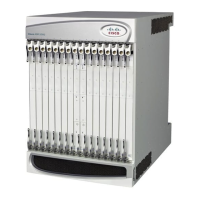
Upper bezel: Covers the upper fan tray bay.
5
Lower fan tray cover/EMI shield: Secures the lower fan tray assembly in place and serves as an EMI shield. The
cover also provides an air baffle allowing air to enter into the chassis.
6
Lower bezel: Covers the lower fan tray bay.
7
Lower fan tray assembly: Draws air into the chassis through the chassis' front and sides for cooling and ventilation. It
is equipped with a particulate air filter to prevent dust and debris from entering the system.
8
Power Filter Units (PFUs): Each of the system’s two 165 amp PFUs provides -48 VDC power to the chassis and its
associated cards. Each load-sharing PFU operates independently from the other to ensure maximum power feed
redundancy.

Table of Contents

Other manuals for Cisco ASR 5000 Series

Questions and Answers:

Question and Answer IconNeed help?

Do you have a question about the Cisco ASR 5000 Series and is the answer not in the manual?

Cisco ASR 5000 Series Specifications

General IconGeneral
BrandCisco
ModelASR 5000 Series
CategoryNetwork Router
LanguageEnglish

Related product manuals