Environmental Specifications
ASR 5000 Installation Guide ▄
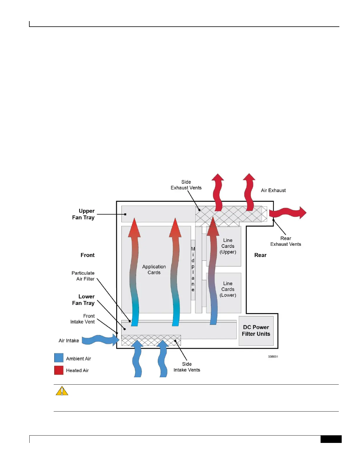
Chassis Air Flow
Airflow within the ASR 5000 is designed per Telcordia recommendations to ensure the proper vertical convection
cooling of the system.
As shown in the figure below, the lower fan tray pulls ambient air into the chassis from the front and side intake vents
located at the bottom of the chassis. The air is pushed upwards through the system and absorbs heat while passing over
system components.
Total air flow exiting the chassis is approximately:
275CFM (7.8 cubic meters/minute) – Low fan speed
565CFM (16 cubic meters/minute) – High fan speed
The upper fan tray pulls the heated air up through the chassis. The heated air then exits through the side and rear exhaust
vents located at the top of the chassis.
Figure 68. System Airflow and Ventilation
Caution: When planning chassis installation, ensure that equipment rack or cabinet hardware does not hinder
air flow at any of the intake or exhaust vents. Additionally, ensure that the rack/cabinet hardware, as well as the ambient
environment, allow the system to function within the operating limits specified in this chapter.

 Loading...


