Cabling the Switch Processor Input/Output Line Card
Connecting to the Management LAN ▀
ASR 5000 Installation Guide ▄
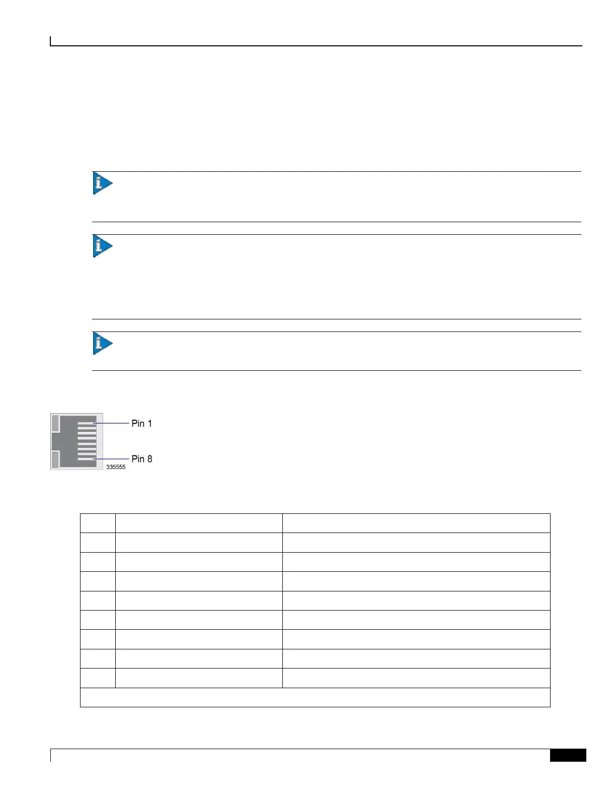
Using the Ethernet RJ-45 Interfaces
The two RJ-45 interfaces are auto-sensing 10/100/1000Base-TX Ethernet interfaces. Refer to the figure and table that
follow for pinouts for the RJ-45 Ethernet ports.
Important: To comply with GR-1089 intra-building, lightning-immunity requirements and ensure compliance
with Radiated Emissions Criteria, you must use shielded-twisted pair (STP) copper cable and ensure that it is properly
terminated at both ends.
Important: The 1000Base-TX (RJ-45) management ports of the SPIO are suitable for connection to intra-
building or unexposed wiring or cabling only. These intra-building ports MUST NOT be metallically connected to
interfaces that connect to the outside plant (OSP) or its wiring. These interfaces are designed for use as intra-building
interfaces only (Type 2 or Type 4 ports as described in GR-1089-CORE, Issue 5) and require isolation from the exposed
OSP cabling. The addition of Primary Protectors is not sufficient protection in order to connect these interfaces
metallically to OSP wiring.
Important: Be sure to label the interface cables with their destination prior to connecting them to the SPIO card.
This will assure proper reconnection should the card need to be serviced.
Figure 31. SPIO Ethernet RJ-45 Interface
Table 33. SPIO Ethernet RJ-45 Interface Pinout
RX = Receive Data TX = Transmit Data BI = BI directional data DA, DB, DC, DD = Data Pair A, B, C, and D

 Loading...


