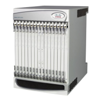
ASR 5000 Hardware Platform Overview
ASR 5000 Installation Guide ▄
Chassis Configurations
The system is designed to scale from a minimum configuration, as shown in the table below, to a fully-loaded redundant
configuration containing a maximum of 48 cards.
If session recovery is enabled, the minimum number of packet processing cards per chassis increases from one to four
cards. Three packet processing cards are active and one packet processing card is standby (redundant). This minimal
configuration is designed to protect against software failures only.
Table 1. Minimum Card Configurations
Supported
ASR 5000
Product
Redundant HW
Configuration
(Note 1)
Redundant HW + SW
Configuration (Note 2)
System Management Card (SMC)
Packet Services Card (PSC)
End of Life (not supported in Release 16.0+)
Packet Services Card Type A
(PSCA)
End of Life (not supported in Release 16.0+)
Packet Services Card 2 (PSC2)
4
(3 active +1 standby)
See Note 3 below.
Packet Services Card 3 (PSC3)
Packet Processing Card (PPC)
End of Life (not supported in Release 16.0+)
Switch Processor I/O (SPIO) Card
Redundancy Crossbar Card (RCC)
Fast Ethernet Line Card (FELC)
End of Life (replaced by FLC2)
Fast Ethernet Line Card 2 (FLC2)
Gigabit Ethernet Line Card (GELC)
End of Life (replaced by GLC2)
Gigabit Ethernet Line Card 2
(GLC2)
Quad Gigabit Ethernet Line Card
(QGLC)
10 Gigabit Ethernet Line Card
(XGLC)

 Loading...


