Cabling the Switch Processor Input/Output Line Card
▀ Connecting to the CO Alarm Interface
▄ ASR 5000 Installation Guide
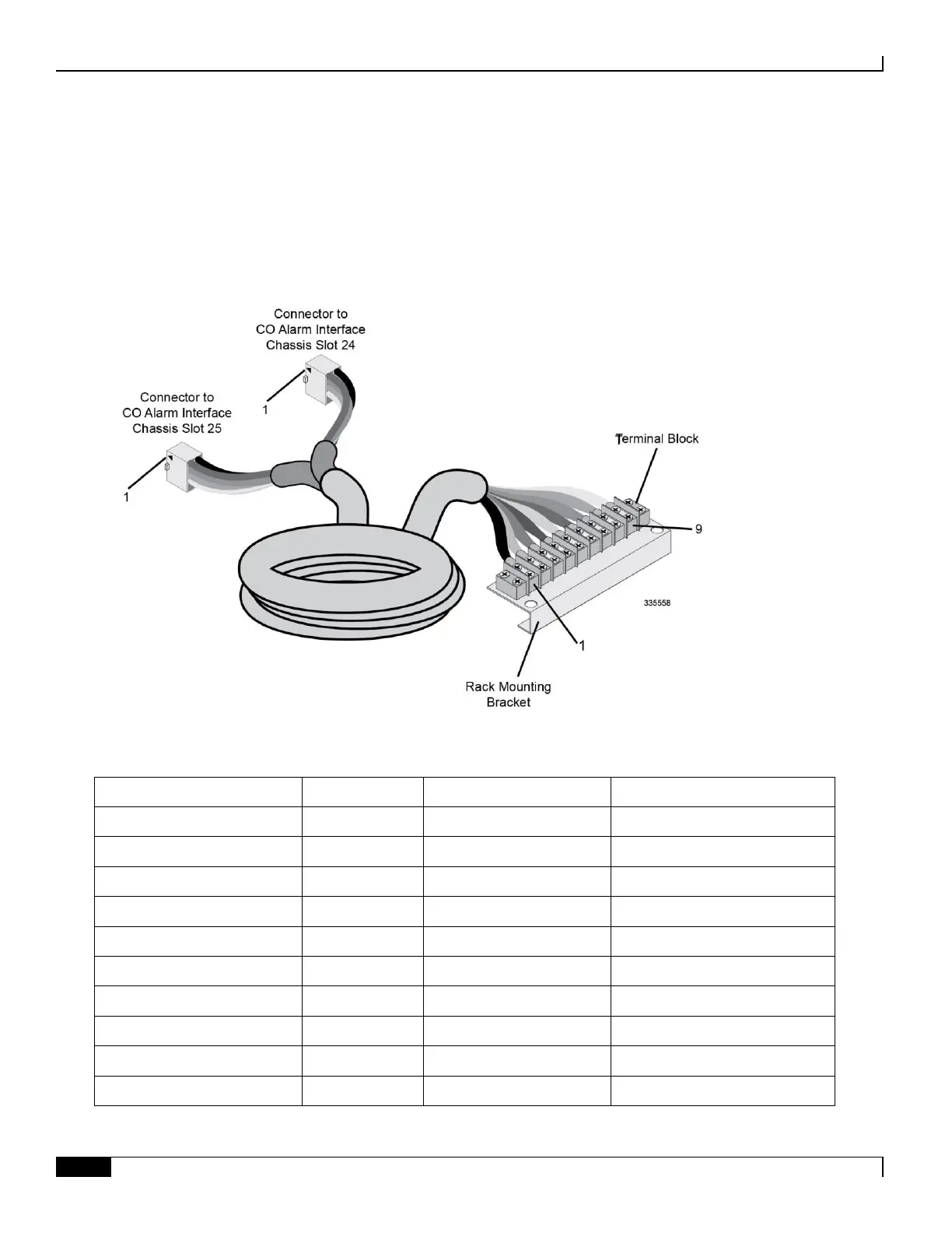
The 8-foot (2.4 meter) CO alarm cable shipped with the chassis supports redundant SPIO card installations. This “Y”
cable has two Molex connectors on one end that are keyed to fit into the CO Alarm interfaces in one direction only.
Each connector mates with one of the side-by-side SPIO cards. On the opposite end is a 9-pin terminal block that you
can mount to the telco cabinet or equipment rack frame.
The following figure and table display this cable assembly and its pinouts.
Figure 39. SPIO CO Alarms Cable Assembly
Table 38. SPIO CO Alarms Cable Assembly Pinout
SPIO CO Alarms IF Pin Number
Terminal Block Position No.
Major Alarm - Normally closed
Major Alarm - Normally open
Minor Alarm - Normally closed
Minor Alarm - Normally open
Critical Alarm - Normally closed
Critical Alarm - Normally open

 Loading...


