ASR 5000 Hardware Platform Overview
ASR 5000 Installation Guide ▄
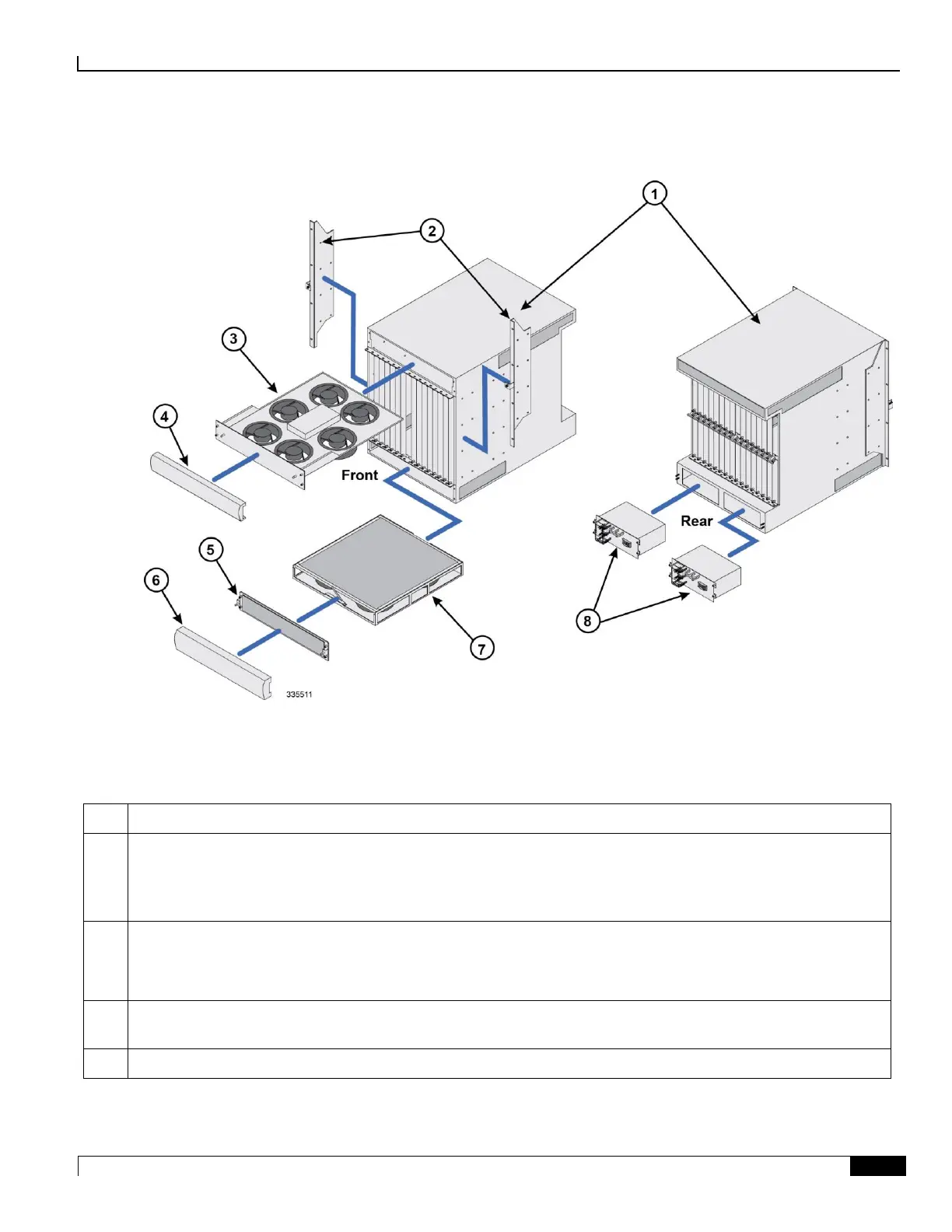
Figure 2. Chassis Components (front and rear views)
This diagram shows exploded views of the front and rear chassis components. They are described below.
Table 2. Chassis and Sub-component Identification Key
Chassis: Supports 16 front-loading slots for application cards and 32 rear-loading slots for line cards. To support the
XGLC, a full-height line card, remove the half-height guide from the rear slots.
The chassis ships with blanking panels over every slot except the following: 1, 8, 17, and 24. These are intentionally
left uncovered for initial installation of application and line cards.
Mounting brackets: Support installation in a standard 19-inch rack or telecommunications cabinet. Flush and mid-
mount options are supported. In addition, each bracket contains an electrostatic discharge jack for use when handling
equipment.
Upper fan tray: Draws air through the chassis for cooling and ventilation. It then exhausts warmed air through the
vents at the upper-rear of the chassis.
Upper bezel: Covers the upper fan tray bay.

 Loading...


