Adding Application and Line Cards to an Existing Installation
▀ Adding Half-Height Line Cards
▄ ASR 5000 Installation Guide
Step 9 Repeat step 1 through step 7 for every other line card that to be installed.
Step 10 Install blanking panels over any unused chassis slots.
WARNING: To reduce the risk of electric shock and to ensure proper ventilation, blanking panels must be used to
cover any chassis slot that is not occupied by an application card. Leere Steckplaetze muessen mit der dafuer
vorgesehenen Abdeckplatte geschlossen werden, um die Luftzirkulation innerhalb des Geraets zu gewaehrleisten und um
einen elektrischen Schlag zu vermeiden.
Step a Position the blanking panel over the unused chassis slot(s).
Step b Use a Phillips #2 screwdriver to tighten the screws at the top and bottom of the blanking panel to
secure the panel to the chassis.
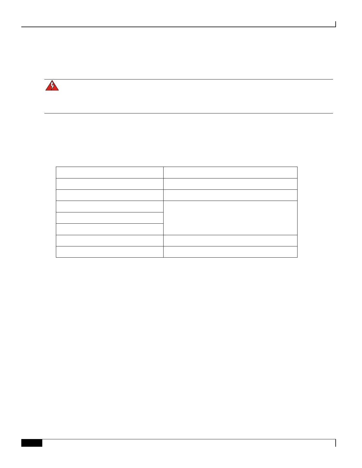
Step 11 Refer to one of the following chapters in this guide for information on cabling the line cards you just installed.
Switch Processor Input/Output (SPIO)
Cabling the Switch Processor Input/Output Line Card
Fast Ethernet Line Card (FLC2)
Cabling the Ethernet 10/100 Line Card
Gigabit Ethernet Line Card (GLC2)
Cabling the Gigabit Ethernet Line Cards
Quad Gigabit Ethernet Line Card (QGLC)
10 Gigabit Ethernet Line Card (XGLC)
Cabling the Optical (ATM) Line Card
Channelized Line Card Interfaces (CLC2)
Cabling the Channelized Line Card

 Loading...


