Installing the Line Card ▀
ASR 5000 Installation Guide ▄
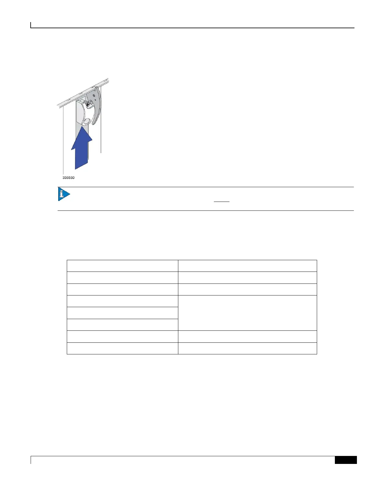
Step 4 Slide the interlock switch on the front panel of the line card upward to lock the ejector tab in place. The flange on the
left-side of the interlock switch prevents movement of the ejector tab when raised completely.
Important: You must slide the interlock switch upward before securing the card’s top screw to the mounting
rail.
Step 5 Use a Phillips #2 screwdriver to tighten the screws at the top and bottom of the line card’s front panel to secure the card
to the chassis.
Step 6 Refer to the destination label on each cable and re-attach the cables to the line card. Refer to the following table to
locate the chapter of this guide that provides information and instructions on cabling the line card.
Switch Processor Input/Output (SPIO)
Cabling the Switch Processor Input/Output Line Card
Fast Ethernet Line Card (FLC2)
Cabling the Ethernet 10/100 Line Card
Gigabit Ethernet Line Card (GLC2)
Cabling the Gigabit Ethernet Line Cards
Quad Gigabit Ethernet Line Card (QGLC)
10 Gigabit Ethernet Line Card (XGLC)
Optical (ATM) Line Card [OLC2]
Cabling the Optical (ATM) Line Card
Channelized Line Card (CLC2)
Cabling the Channelized Line Card

 Loading...


