ASR 5000 Hardware Platform Overview
ASR 5000 Installation Guide ▄
The GLC2 supports the Star Channel (1 Gbps) for faster FPGA upgrades and is Restriction of Hazardous Substances
(RoHS) 6/6 compliant.
The GLC2s can be installed in chassis slots 17 through 23, 26 through 39, and 42 through 48. These cards are always
installed directly behind their respective or packet processing cards, but they are not required behind any redundant
packet processing cards (those operating in Standby mode).
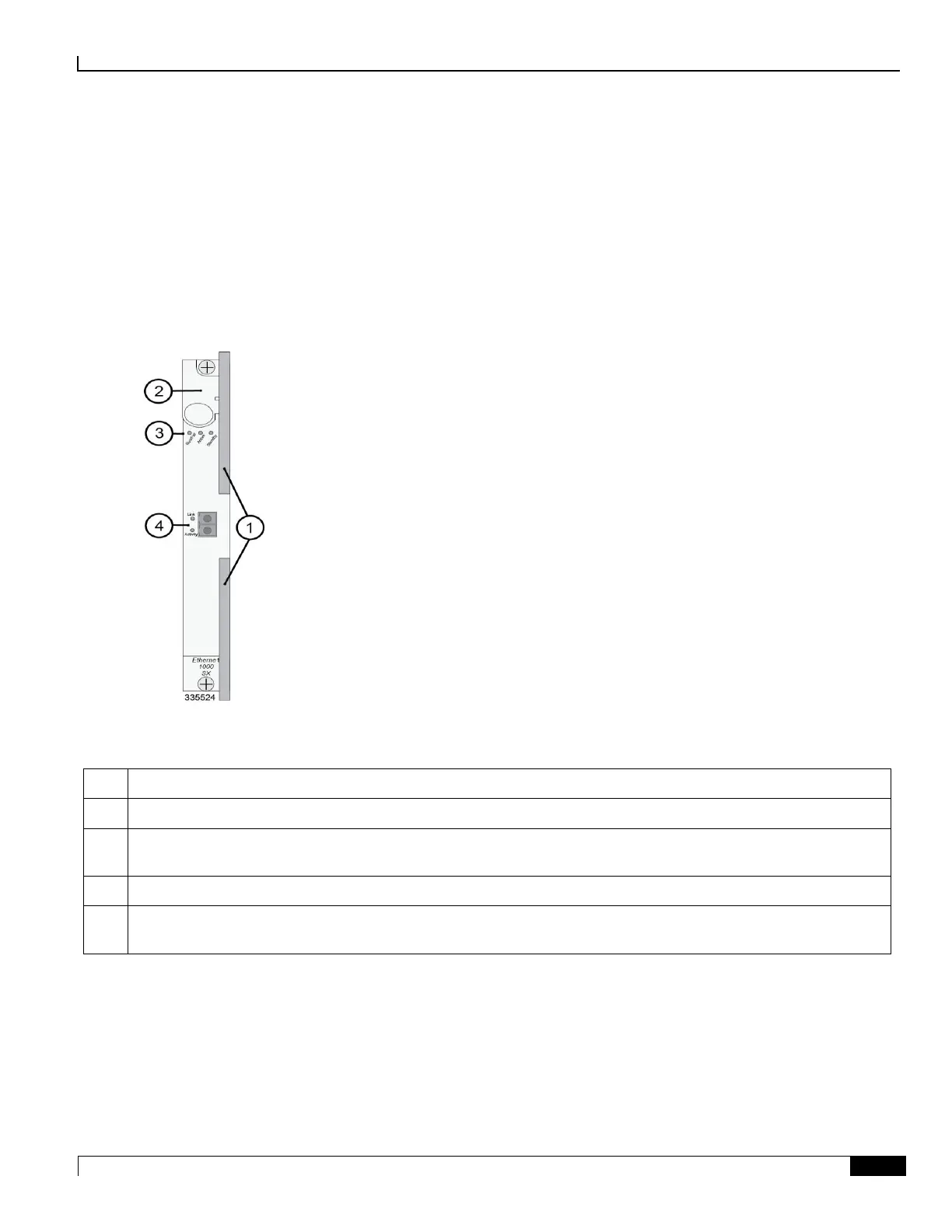
The following diagram shows the front panel of the GLC2 with an optical connector, identifying its interfaces and major
components.
Figure 15. Gigabit Ethernet Line Card (GLC2)
Table 13. GLC2 Callouts
Card Ejector Levers—Use to insert/remove card to/from chassis.
Interlock Switch—In its Down position, the interlock switch notifies system to safely power down card prior to
removal.
Card Level Status LEDs—Show the status of the card. See Applying Power and Verifying Installation for definitions.
Gigabit Ethernet Interface—Gigabit Ethernet (GE) SFP modules.
1000Base-SX, 1000Base-LX, and 1000Base-T interfaces are supported depending on the SFP module installed.

 Loading...


