ASR 5000 Hardware Platform Overview
ASR 5000 Installation Guide ▄
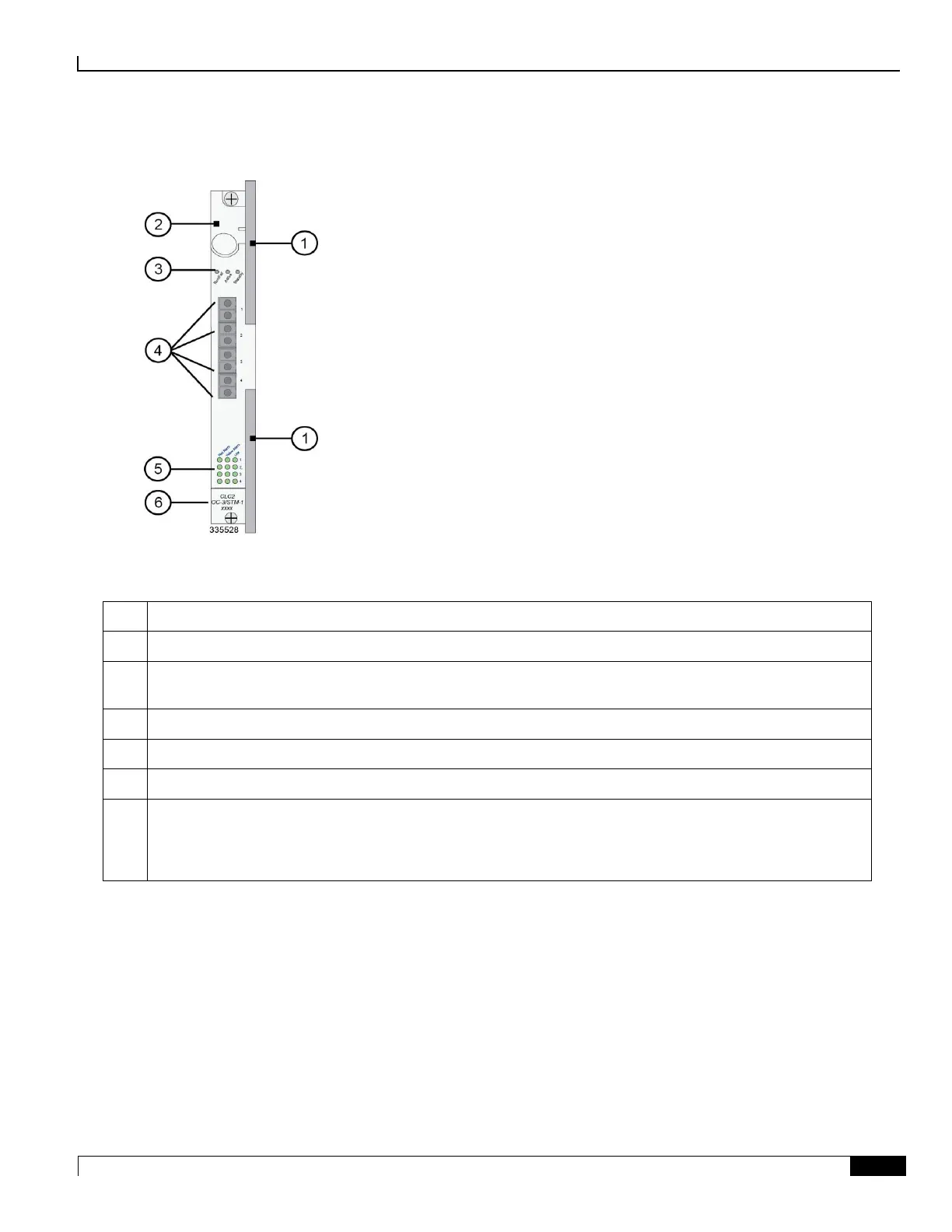
Figure 19. Channelized Line Card (CLC2)
Table 21. CLC2 (Frame Relay) Callouts
Card Ejector Levers—Use to insert/remove card to/from chassis.
Interlock Switch—In its Down position the interlock switch notifies the system to safely power down the card
prior to its removal.
Card Level Status LEDs—Show the status of the card.
Port connectors—Fiber LC duplex female connector.
Port Level Status LEDs—Show the status of a port.
Line Card Label—Identifies the type of SFP modules and cabling supported:
CLC2, OC-3/STM-1, Single Mode
CLC2, OC-3/STM-1, Multi-Mode
The Channelized Line Card (CLC2) was developed in compliance with the following standards:
ITU-T - Recommendation G.704 - Synchronous Frame Structures Used at 1544, 6312, 2048, 8448 and 44736
kbps Hierarchical Levels, October, 1998.
ITU-T - Recommendation G.706 - Frame Alignment and Cyclic Redundancy Check (CRC) Procedures Relating
to Basic Frame Structures Defined in Recommendation G.704, April 1991.
ITU-T - Recommendation G.707 Network Node Interface for the Synchronous Digital Hierarchy (SDH),
December 2003.
ITU-T - Recommendation G.747 Second Order Digital Multiplex Equipment Operating at 6312 kbps and
Multiplexing Three Tributaries at 2048 kbps, 1993.

 Loading...


