▀ Chassis Slot Numbering and Assignments
▄ ASR 5000 Installation Guide
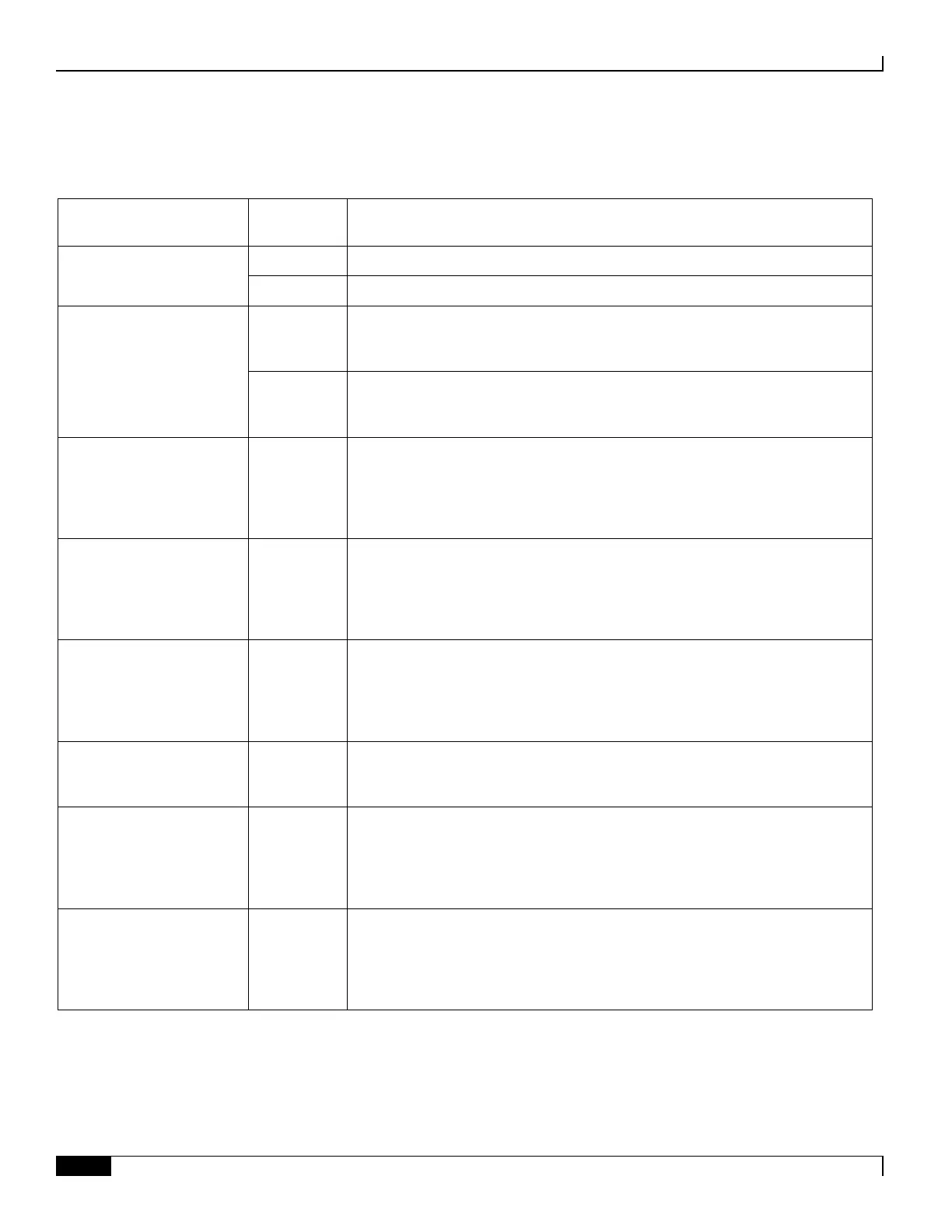
Table 28. Line Card Slot Assignments
Switch Processor
Input/Output (SPIO)
Resides behind Primary SMC in slot 8.
Resides behind Redundant SMC in slot 9.
Redundancy Crossbar Card
(RCC)
Resides behind Primary SMC in slot 8. It provides redundancy for all packet
processing application cards and for line cards installed in the upper-rear chassis,
slots 17 through 23 and 26 through 32.
Resides behind Redundant SMC in slot 9. It provides redundancy for all SMC
application cards and for line cards installed in the lower-rear chassis, slots 33
through 39 and 42 through 48.
17 through
23, 26
through 39,
or 42
through 48
Resides directly behind its corresponding packet processing card. Each packet
processing card can support up to two FLC2s. The active card is installed in the
upper rear chassis slot. The redundant card is installed in the lower rear chassis
slot.
17 through
23, 26
through 39,
or 42
through 48
Resides directly behind its corresponding packet processing card. Each packet
processing card can support up to two GLC2s. The active card is installed in the
upper rear chassis slot. The redundant card is installed in the lower rear chassis
slot.
17 through
23, 26
through 39,
or 42
through 48
Resides directly behind its corresponding packet processing card. Each packet
processing card can support up to two QGLCs. The active card is installed in the
upper rear chassis slot. The redundant card is installed in the lower rear chassis
slot.
10 Gigabit Ethernet Card
(XGLC)
17 through
23 and 26
through 32
Resides directly behind its corresponding packet processing card. The XGLC is a
full-height line card that occupies the upper and lower slots in the ASR 5000.
17 through
23, 26
through 39,
or 42
through 48
Resides directly behind its corresponding packet processing card. Each packet
processing card can support up to two OLC2s. The active card is installed in the
upper rear chassis slot. The redundant card is installed in the lower rear chassis
slot.
7 through
23, 26
through 39,
or 42
through 48
Resides directly behind its corresponding packet processing card. Each packet
processing card can support up to two CLC2s. The active card is installed in the
upper rear chassis slot. The redundant card is installed in the lower rear chassis
slot.

 Loading...


