Citrix SD-WAN Platforms
The front panel of the SD-WAN 1000 with Windows Server appliance has a power button and five LEDs.
The power button is used to switch the appliance on or o.
The reset button restarts the appliance.
The LEDs provide critical information related to dierent parts of the appliance.
• Power Fail – Indicates the power supply unit has failed.
• Information LED – Indicates the following:
| Status | Description |
|—|—|
| Continuously ON and red | The appliance is overheated. (This might be a result of cable con-
gestion.) |
| Blinking red (1Hz) | Fan failure, check for an inoperative fan. |
| Blinking red (0.25Hz) | Power failure, check for the non-operational power supply. |
| Solid blue | Local UID has been activated. Use this function to locate the server in a rack mount
environment. |
| Blinking blue (300 m/s) | Remote UID is on. Use this function to identify the server from a re-
mote location. |
• NIC1 and NIC2 – Indicate network activity on the LAN1 and WAN1 ports.
• HDD – Indicates the status of the hard disk drive.
• Power – Indicates that the power supply units are receiving power and operating normally.
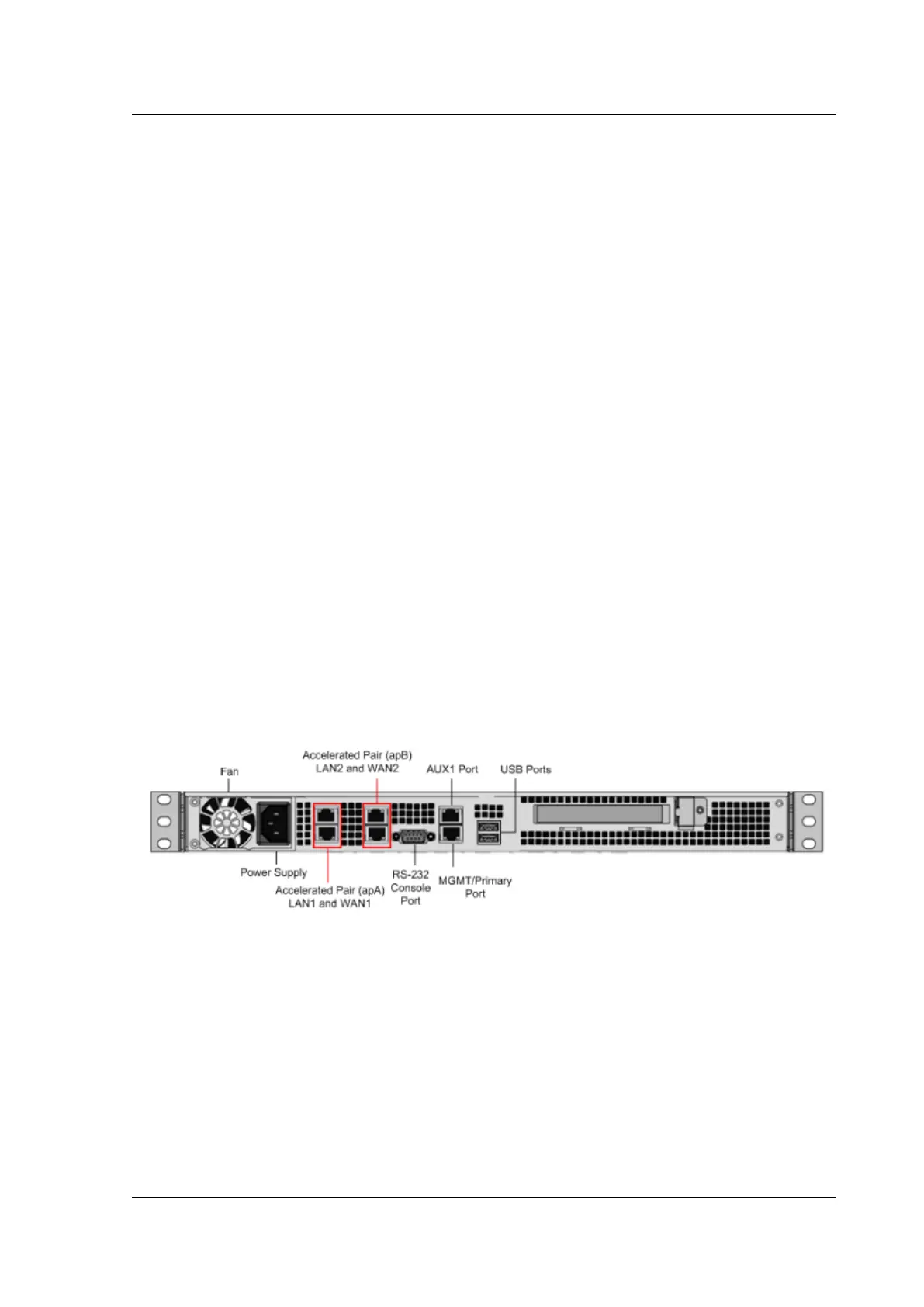
The following figure shows the back panel of a SD-WAN 1000 appliance with Windows Server.
Figure 2. Citrix SD-WAN 1000 appliance with Windows Server , back panel
The following components are visible on the back panel of a SD-WAN 1000 appliance with Windows
Server:
• Cooling fan
• Single power supply, rated at 200 watts, 110-240 volts
• Accelerated pairs of Ethernet ports (apA and apB) which function as accelerated bridges
• RS-232 serial console port
• One AUX Ethernet port and one management port
• Two USB ports
© 1999-2021 Citrix Systems, Inc. All rights reserved. 23
 Loading...