Removal and replacement of ADU modules
99-145912-A Chapter 8: Service & maintenance 8-19
• Connection to the BLDCM, and delivering the required phase
current to the motor.
• Decoding the HALL-sensor input from the Zero Reference Module
(ZRM).
• Decoding the input from the Optical Rotary Encoder (ORE).
• Incorporating a break function when not powered.
6. Cross elevation motor and encoder.
7. Zero Reference Module (x3) (ZRM) (not visible on photo). (2 in the
figure above, i in the figure below.
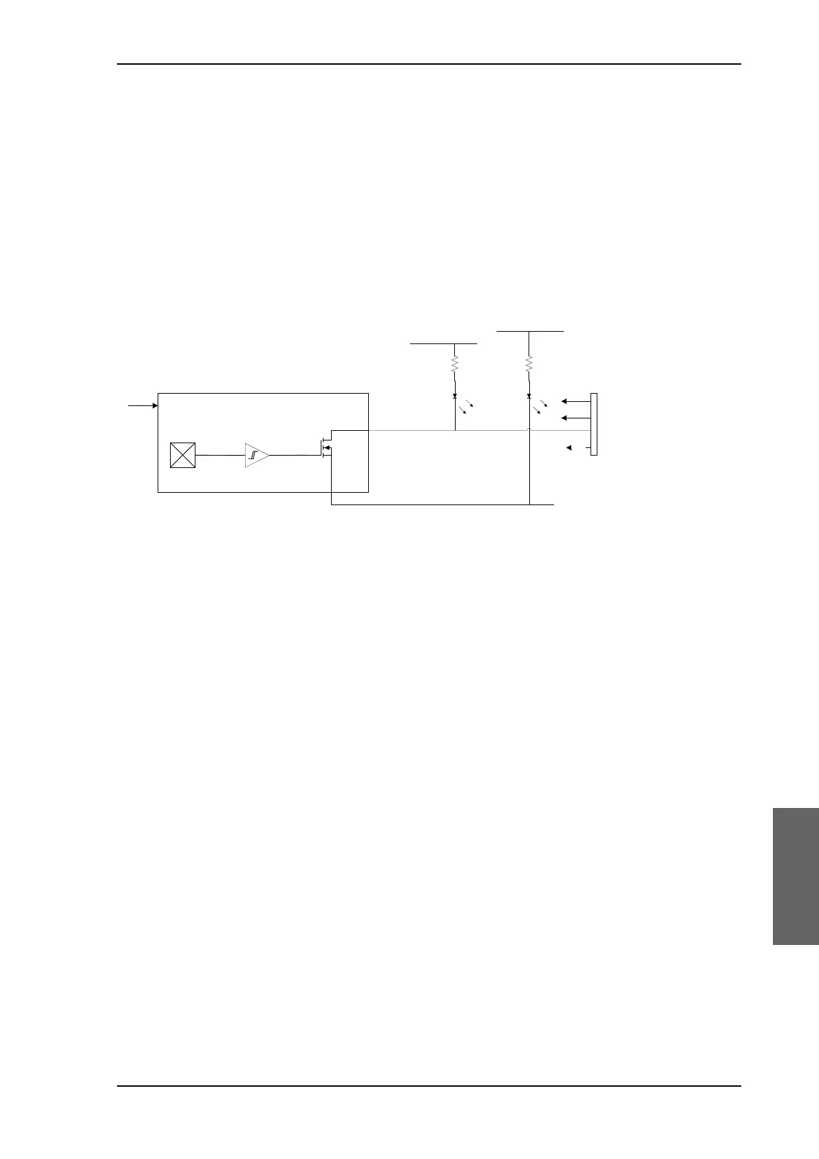
In order to be able to find the predefined zero point of the antenna
direction, HALL sensors and corresponding magnets mount in the
gearwheels. Due to the magnetic hysteresis behaviour of the hall
sensor, the software will have to make the magnets pass the hall
sensor in both directions, and when use the mean value as the zero
point.
The ZRM features two LEDs; one for indication of power supply, and
one for indication of zero point.
8. DC-Motor Driver Module for elevation (on the bottom side) (DDM).
As in item 3 above.
9. Elevation motor and encoder (not visible).
10.BUC Control Module (BCM).
TBD: STA?
11.Block Up Converter (BUC). (behind cable screen, not visible on photo)
The BUC converts the L-band Intermediate Frequency (IF) up to Ka-
band radio signal, and amplifies it to transmit power level. It receives
transmit signal and power from VIM2.
12.Low Noise Block down converter (LNB).
The LNB receives the Ka-band radio signal, amplifies it and converts it
down to an L-band Intermediate Frequency (IF). The conversion is
controlled by a Local Oscillator (LO) frequency and the LO frequency
is locked to an external reference signal. DC power and 50 MHz
external reference signal are also supplied over the IF cable. The L-
Figure 8-14: ZRM – Block diagram
ZeroSensor
Allegro A1102ELHLT-T
5VS
gnd
5VS
gnd
5VS
LEDLED
3V3
3V3

 Loading...


