Removal and replacement of ADU modules
8-20 Chapter 8: Service & maintenance 99-145912-A
band IF output is routed to the VSAT Interface Module (VIM2)
located on the ADU's azimuth pedestal.
13.Polarizer.
The PMM provides power and communicates with the BUC. Control
signals forwarded by VIM2 from BDU via coax cable are
demodulated and sent to BUC for correct functionality.
The PMM board is:
• Communication slave of the ADU Bus also connecting the
DCmotor Driver Modules (DDM), the Inertial Sensor Module
(ISM) and the Pedestal Control Module (PCM).
• (Detection of temperature and power level from the Ortho Mode
Transducer (OMT) - OPTIONAL)
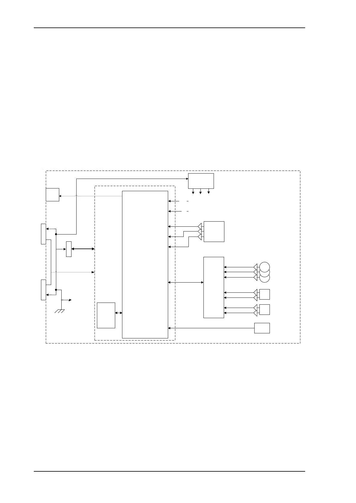
14.Inertial Sensor Module (ISM).
The ISM shall — based on request from the PCM — provide
information about movement of the parabolic reflector, in the form
of samples from gyro- and acceleration-sensors.
The ISM board is:
• Communication as slave of the ADU Bus connecting the Inertial
Sensor Module (ISM), the DC-motor Driver Modules (DDM), the
Polarization Motor Module (PMM), and the Pedestal Control
Module (PCM).
• Collection of contemporary sample-data sets from all sensors
and provide those to the PCM on request. A set of samples
should be collected within less than 100 micro seconds.
Figure 8-15: ISM – Block diagram
'LJLWDO&RQWURO
)LOWHU/'2V
9'
96
9
0&8
,60
)ODVK
&DOLEUDWLRQ
GDWD
0RGXOH,'
*\UR
[$FF
=
=<
7HPS
VHQVRU
[$FF
;<
9
6 2 6 8
*\UR
<
*\UR
;
[
$FF
9P96
6WDWXV
/('V
9
9P
;
<
=
([W
([W
([W
([W
([W
([W
([W
([W
5HI9'
;
<
<
=
56
6%XV
JQG
6%XV
6XE' 6XE'
$GGU
6HULDO$GGU

 Loading...


