Removal and replacement of ADU modules
99-145912-A Chapter 8: Service & maintenance 8-21
• High stability and accuracy 3 axis accelerometer and angular rate
sensor.
• Prepared for wide range 3 axis accelerometer.
• Calibration of sensor offset, gain, and misalignment over
temperature (stored in non-volatile memory).
• Secure fixing to the parabolic reflector.
• Diagnosis of board supplies, sensor inputs, etc.
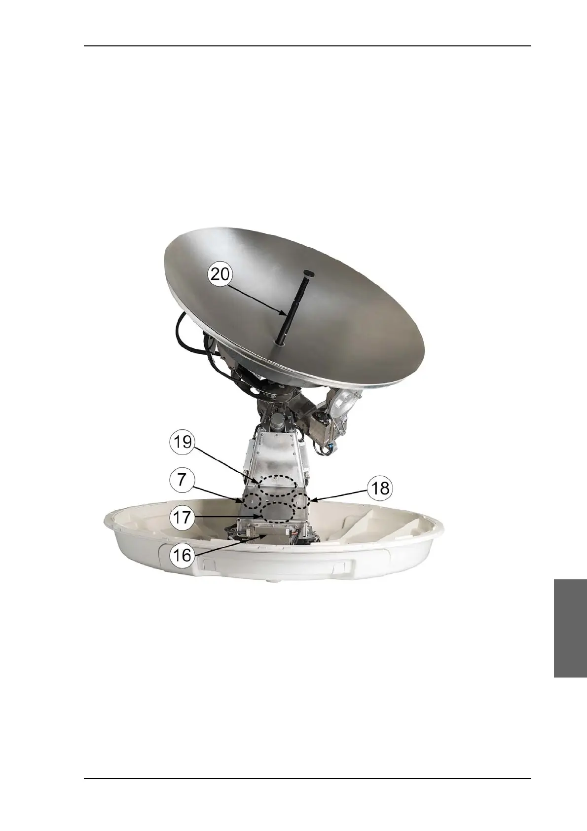
15.Elevation locking pin to lock the antenna dish in a fixed position (for
safety during service) (not visible on photo).
16.DC-Motor Driver Module for Azimuth (DDM).
As in item 3 above.
17.Azimuth motor.
18.Azimuth encoder.
19.Rotary joint.
The cable signals for the ADU (DC power, internal modem
communication, TX IF, RX and L-band TX) to and from the ACU have
Figure 8-16: Above Deck Unit modules 2/2

 Loading...


