Page 2 of 6
While the P4 system communicate through the CAN bus, and certain devices (such as NF4 and TS4) are
powered by the network power, the SPU and the P4 Head require local power supply.
Power Supply to SPU
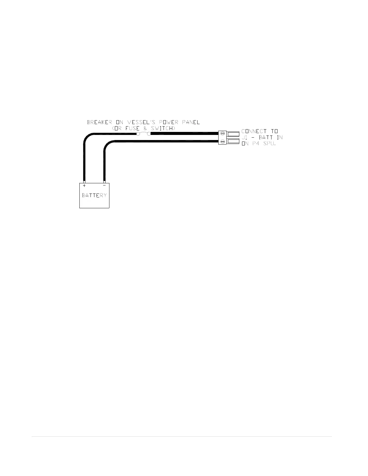
The Figure A.1 shows the power supply connection to the SPU. J1 of the SPU box is the local power
supply port for the SPU. Fuses are built into the SPU unit. However, a remote disconnect switch or a
circuit breaker must still be installed in line with the power input to the SPU. Make sure it is rated at a
greater than or equal value to 25 Amps. This breaker will serve as your autopilot ultimate safety
“OFF” switch in case the network-based controllers have lost communication to the SPU.
Figure A.1 – Power Supply connection to the SPU. A circuit breaker must be installed.
The location of the SPU unit it should be placed to minimize length of wiring. It is most important to
minimize the runs of power and motor leads since voltage drop in these cables will reduce steering
power.
Power Supply to P4 Head
The Figure 24 in the manual shows the typical battery connection to a P4 head. A P4 Head wired like that
is one control Station. When a station turns on, it starts from the “repeater” status, meaning it monitors all
data from the SPU but cannot operate the SPU. The user has to switch the Head to the “command”
status before it can be used to control the SPU.
A Master station is the one that will automatically place itself to the “command” status after the device is
turned on. To wire a P4 Head to a Master station, connect the brown terminal of the P4 head power cable
to the negative battery terminal as shown in Figure A.2 below. If you have more than one P4 Heads, only
one of them should be wired as a Master station.