ISM-8 – AXIS SETUP
5.2.3 AXIS CHANNELS, AXIS DISPLAY, INVERT AXIS DIRECTION AND AXIS NAME
These parameters set:
Which actuator motor channels on the ISM-8 will operate for a particular axis.
The user display for a particular axis.
Whether a channel direction is inverted for a particular axis.
Sets the text to be displayed on the LCD when the associated Actuator Axis is selected.
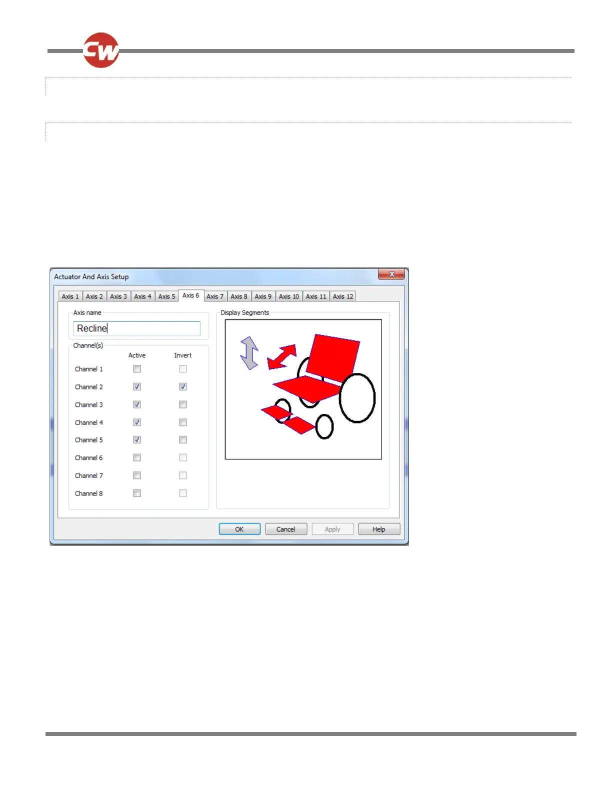
These options are in the form of a dialogue box, as shown in the following example diagram.
In this example, Axis 6 is the Axis that is being set-up. With the programming as shown: Channels 2, 3, 4 and 5 will operate in
this Axis; the direction of Channel 2 is inverted, i.e. when the joystick is deflected forwards, the channel outputs will hav e pin 2
negative with respect to pin 1; and the Joystick Module will highlight those areas colored in red.
NOTE:
The outline of the whole wheelchair symbol is always present on the user display, but with the elements highlighted as
defined in red. However, if the arrow symbols are not defined in red, they will not appear on the display.
When the dialogue box is closed, the programming is expressed as follows: