Application Guide | iC2-Micro Frequency Converters
3.2.5 Control Panel 2.0 OP2 Buttons and Indicators
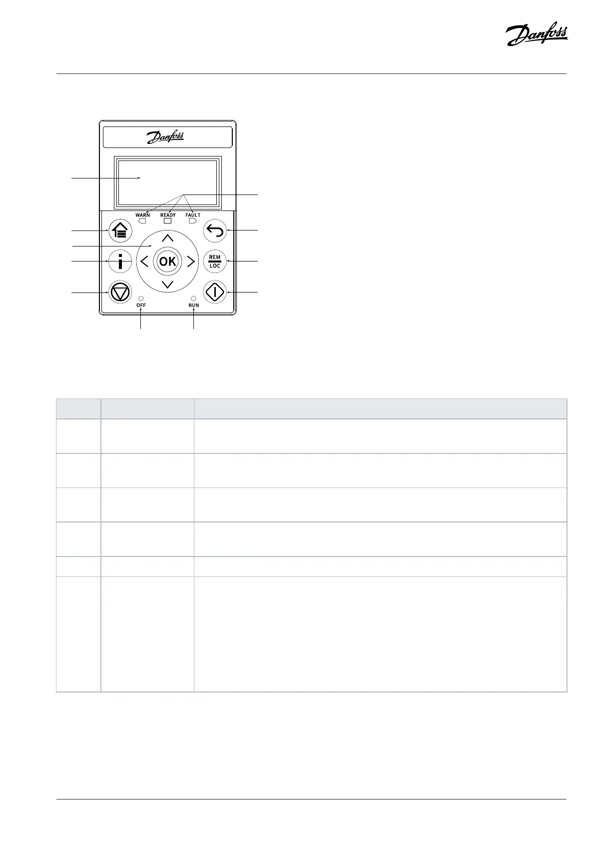
Figure 9: Control Panel 2.0 OP2 Overview
Table 7: Control Panel Elements Description
Legend Name of element Description
1 Display Provides access to content and settings. The display provides detailed information about the sta-
tus of the drive.
2 Home/Menu • Toggles between status view and main menu.
• Long press to access the shortcut menu for quickly reading and editing parameters.
3 Arrows and [OK] • Arrows: Navigate within the different screens and menus, and tune the parameter values.
• [OK]: Confirms selections and data in the control panel display.
4 Info Provides drive information by pressing the Info button from the home screen, for example, the
drive type, ordered model code, drive serial number, application version.
5 Stop/Reset Stops the operation of the drive.
6 OFF LED The indicator has the following states:
• Steady on: The indicator is in this state when:
- The drive is not modulating and the drive is coasted.
- The stop or coast signal is applied. Ramp times, protections, and stopping functions might
prolong this state.
• Off: The drive is in operation, a start signal is applied, and the output is active. This also
includes ramping, running on reference, and AMA.
Danfoss A/S © 2024.03 AB413939445838en-000301 / 130R1254 | 29