Application Guide | iC2-Micro Frequency Converters
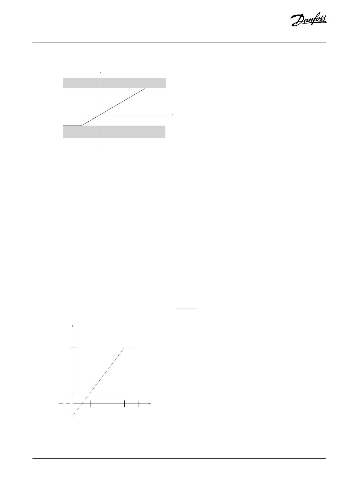
Reference range = Minimum to maximum
Resulting reference
Maximum reference
Minimum reference
Sum of all
references
Figure 46: Sum of all References when Configuration Mode is set to Process
5.6.3 Scaling of Preset References and Bus References
Preset references are scaled according to the following rules:
l When P 5.5.3.1 Reference Range is set to [0] Min–Max, 0% reference equals 0 [unit] where unit can be any unit, for example RPM,
m/s, and bar. 100% reference equals the maximum (absolute value of P 5.5.3.3 Reference Maximum, absolute value of P 5.5.3.4
Reference Minimum).
l When P 5.5.3.3 Reference Range is set to [1] -Max–+Max, 0% reference equals 0 [unit], and 100% reference equals maximum
reference.
Bus references are scaled according to the following rules:
l When P 5.5.3.1 Reference Range is set to [0] Min–Max, 0% reference equals minimum reference and 100% reference equals
maximum reference.
l When P 5.5.3.1 Reference Range is set to [1] -Max–+Max, -100% reference equals -maximum reference, and 100% reference equals
maximum reference.
5.6.4 Scaling of Analog and Pulse References and Feedback
References and feedback are scaled from analog and pulse inputs in the same way. The only difference is that a reference above or below
the specified minimum and maximum endpoints (P1 and P2 in the Figure 47) are clamped while feedbacks above or below are not.
Resource input
Terminal X
high
High reference/
feedback value
Low reference/
feedback value
Figure 47: Minimum and Maximum Endpoints
Danfoss A/S © 2024.03 AB413939445838en-000301 / 130R1254 | 69