Application Guide | iC2-Micro Frequency Converters
Table 52: Lower Register Numbers for Input and Output Data (continued)
02910 output data Frequency converter status word register (STW)
02911 output data Frequency converter main value register (MAV)
Master-follower
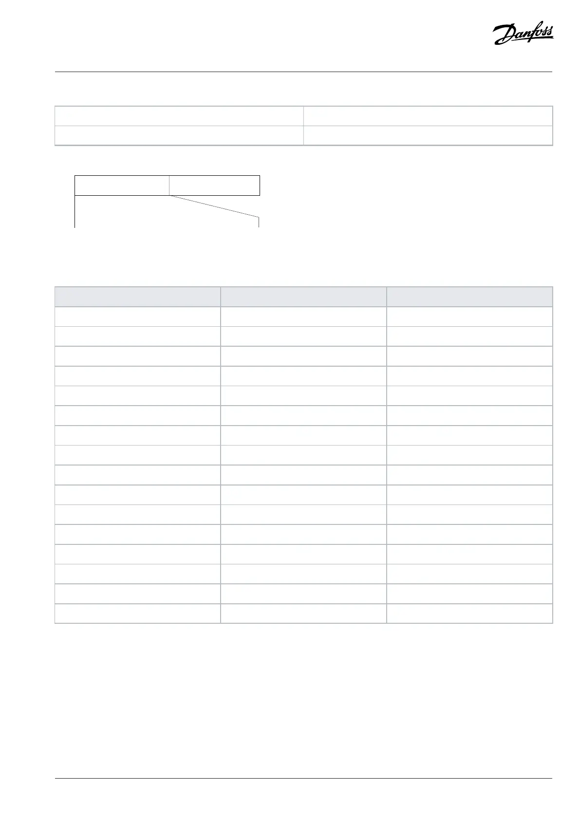
e30ba274.11
15 14 13 12 11 10 9 8 7 6 5 4 3 2 1 0
Figure 65: Control Word According to FC Profile
Table 53: Control Word According to FC Profile
Bit Bit value = 0 Bit value = 1
00 Reference value External selection lsb
01 Reference value External selection msb
02 DC brake Ramp
03 Coasting No coasting
04 Quick stop Ramp
05 Hold output frequency Use ramp
06 Ramp stop Start
07 No function Reset
08 No function Jog
09 Ramp 1 Ramp 2
10 Data invalid Data valid
11 Relay 01 open Relay 01 active
12 Reserved Reserved
13 Parameter setup Selection lsb
14 Reserved Reserved
15 No function Reverse
6.1.8.2 Explanation of Control Word Bit
Bits 00/01
Bits 00 and 01 are used to select among the 4 reference values, which are preprogrammed in P 5.5.3.10 Preset Reference according to the
following table.
Danfoss A/S © 2024.03 AB413939445838en-000301 / 130R1254 | 97