Application Guide | iC2-Micro Frequency Converters
Table 8: Legend Table
Legend Description
1
• The front number indicates active setup.
(1)
• The number in brackets indicates the programming setup.
(2)
2 • On Readout Screens, the value with unit after the setpoint icon is the reference setting data.
• On Menu Screens, the value with unit (no setpoint icon) is the output data.
3 Direction icon: indicates the direction of motor rotation.
4 LOC/REM: indicates local or remote control mode.
• LOC: local control mode.
• REM: remote control mode.
5 Middle value: indicates the readouts value.
6 Readout type
1) Select active setup in P 6.6.1 Active Setup.
2) Select programming setup in P 6.6.2 Programming Setup.
Readout type selection
Press the up and down arrow on the Control Panel 2.0 OP2 when in the Readout Screen. The control panel screen navigates to the readout
items in order. See 3.2.4.2 Understanding Readout Screens.
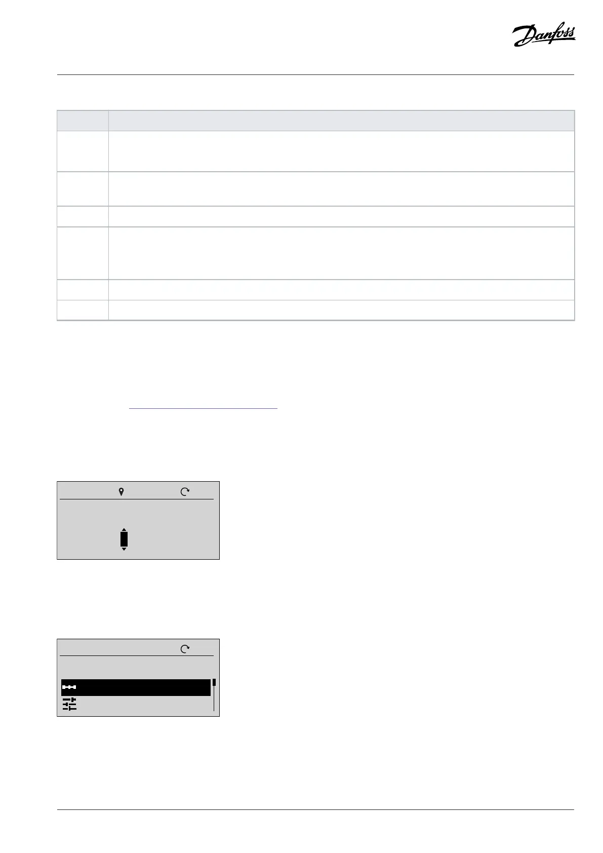
Reference setting in local mode
In local mode, press the OK button on Readout Screen to enter the reference setting. The reference value is valid immediately via pressing
up, down, and left arrows for setting.
Figure 11: Setting the Reference Value
3.2.6.3 Menu Screen and Navigation
Use the Home/Menu button to toggle between Readouts Screen and Menu Screen.
Quick Access
All Parameters
Figure 12: Menu Screen
Main menu includes different functions which are shown in the following table.
Danfoss A/S © 2024.03 AB413939445838en-000301 / 130R1254 | 31