4.2.5 29-5* Flow Conrmation
The ow conrmation feature is designed for applications
where there is a need for the motor/pump to run while
waiting for an external event. The ow conrmation
monitor expects to get a digital input from a sensor on a
gate valve, ow switch, or a similar external device
indicating that the device is in the open position and ow
is possible. In 29-50 Validation Time, a user denes how
long the VLT
®
AQUA Drive FC 202 waits for the digital
input signal from the external device to
conrm the ow.
After the ow is conrmed, the adjustable frequency drive
checks the signal again after the ow verication time and
then runs normally. The LCP status reads "Verifying ow"
while the ow monitor is active.
The adjustable frequency drive trips with the alarm Flow
Not
Conrmed, if the expected digital input signal becomes
inactive before either the ow validation time or the ow
verication time expires.
130BD766.10
N
MAX
N
MIN
0
0
1
1
0
1
0
1
2
3
4
t0 <t1 t2
T
T
T
T
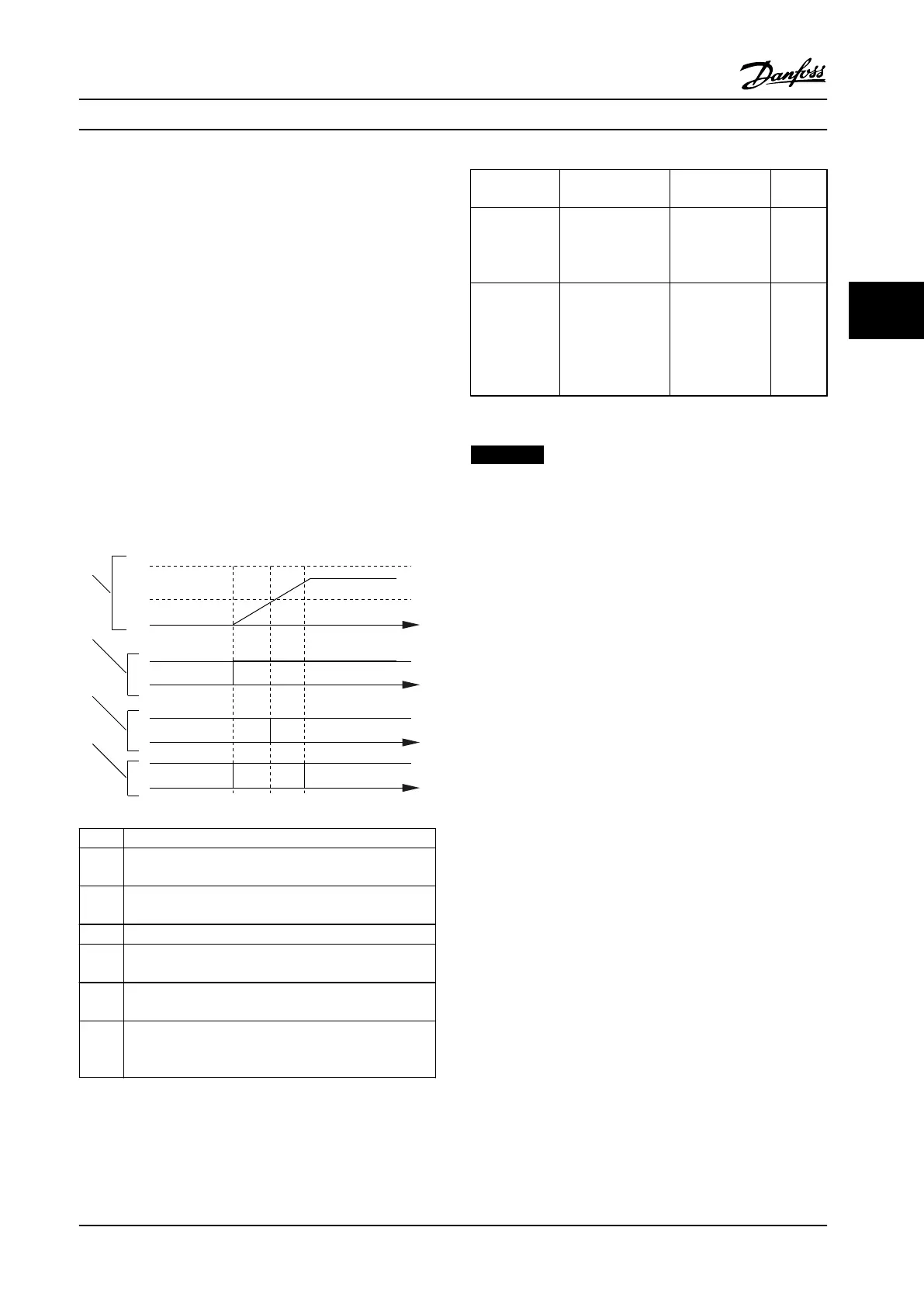
1 Speed curve
2 Start command (for example, terminal 18)
3 Digital signal from an external device that conrms that
the ow is possible.
4 Flow verication
t
0
Start command issued (for example, terminal 18 is set
active)
t
1
Digital signal from an external device becomes active
before 29-50 Validation Time expires.
t
2
When 29-51 Verication Time passes, the adjustable
frequency drive checks the signal from the external
device again and then runs normally.
Figure 4.3 Flow Conrmation
Parameter and
Name
Description Settings Unit
29-50 Validatio
n Time
The digital input
must be active
during the
validation time.
0.1–999.0
(*size dependent)
s
29-51 Veri-
cation Time
Flow will be
conrmed if, at the
end of the veri-
cation time, the
digital input is still
active.
0.1–255.0
(*15)
s
Table 4.2 Flow Conrmation Parameters
NOTICE!
The parameters are only visible on the LCP when a
digital input is congured as ow conrmation.
4.2.6 Advanced Minimum Speed
Monitoring for Submersible Pumps
Some pumps are very sensitive to operating at low speed.
Typical reasons for this are insucient cooling or
lubrication at low speed.
Under overload conditions, the adjustable frequency drive
protects itself using its integral protection features, which
include lowering the speed. For example, the current limit
controller can lower the speed. This means that, in some
cases, the speed may go lower than the speed specied in
4-11 Motor Speed Low Limit [RPM] and 4-12 Motor Speed
Low Limit [Hz].
The advanced minimum-speed monitoring feature trips the
adjustable frequency drive if the speed drops below a
certain value. If the pump motor of the pump does not
reach the speed
specied in 1-86 Trip Speed Low [RPM]
within the time specied in 1-79 Pump Start Max Time to
Trip (ramping up takes too long), the adjustable frequency
drive trips. Timers for 1-71 Start Delay and 1-79 Pump Start
Max Time to Trip start at the same time when the start
command is issued. For instance, this means that if the
value in 1-71 Start Delay is more than or equal to the value
in 1-79 Pump Start Max Time to Trip, the adjustable
frequency drive never starts.
Application Examples
Design Guide
MG20N622 Danfoss A/S © 09/2014 All rights reserved. 103
4 4

 Loading...


