7.11.4
VLT
®
Extended Relay Card MCB 113
The MCB 113 extends the I/O of the adjustable frequency
drive by seven digital inputs, two analog outputs, and four
SPDT relays. The extended I/O increases exibility and
enables compliance with the German NAMUR NE37
recommendations.
The MCB 113 is a standard C1 option and is automatically
detected after mounting.
130BA965.10
121110987654321
4321 12111098765432121 13 14
+
-
+
-
+
-
+
-
+
-
+
-
+
-
+
-
+
-
+
-
A03
A03
Ext. 24 VDC
DI1
DI2
DI3
DI4
DI5
DI6
DI7
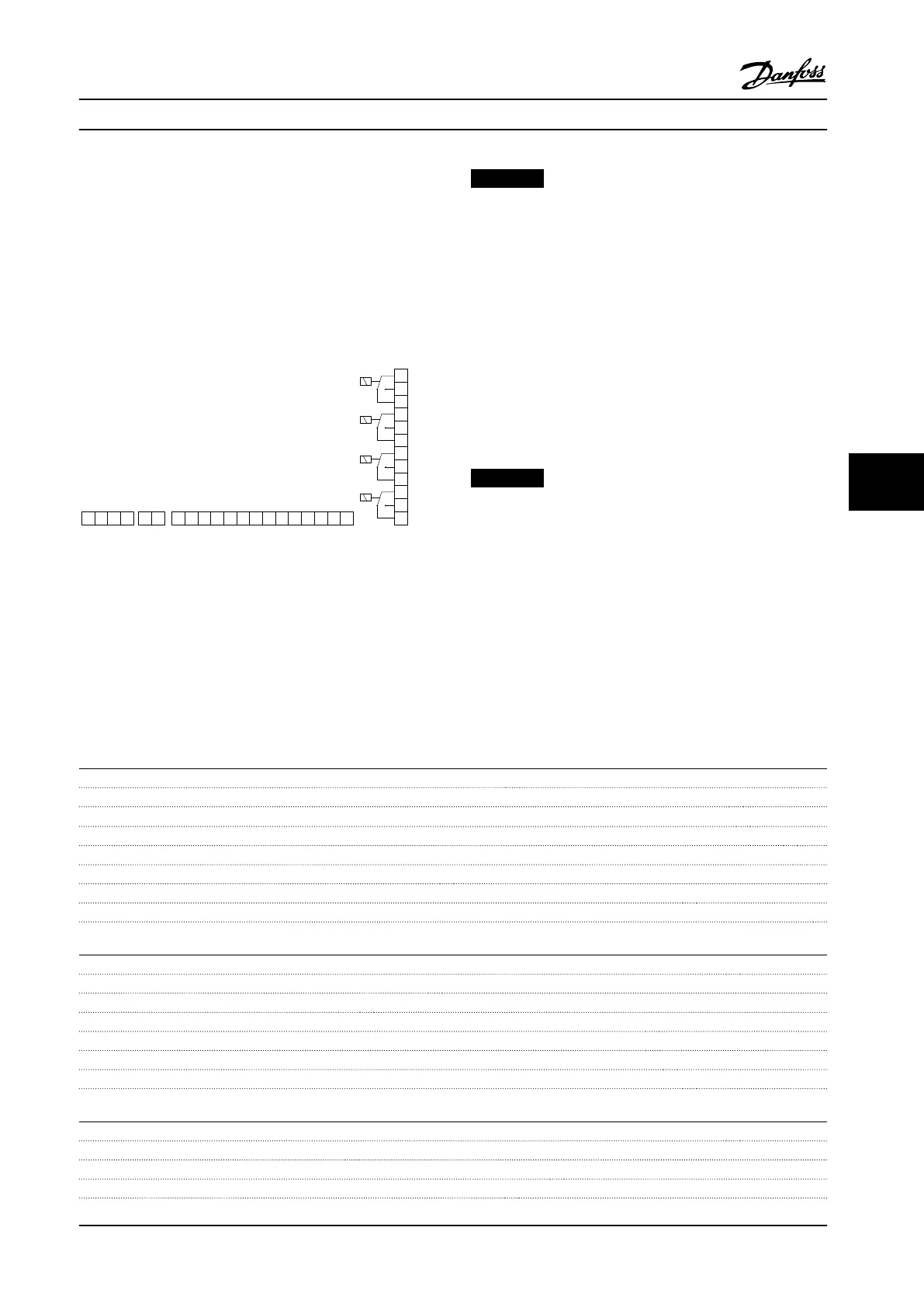
X45/ X48/ X46/
X47/
Relay 3 Relay 4 Relay 5 Relay 6
Figure 7.11 Electrical Connections of MCB 113
To ensure galvanic isolation between the adjustable
frequency drive and the option card, connect MCB 113 to
an external 24 V on X48. When galvanic isolation is not
required, the option card can be supplied through internal
24 V from the adjustable frequency drive.
NOTICE!
To connect both 24 V signals and high-voltage signals in
the relays, ensure that there is one unused relay
between the 24 V signal and the high-voltage signal.
To set up MCB 113, use parameter groups:
•
5-1* Digital input
•
6-7* Analog output 3
•
6-8* Analog output 4
•
14-8* Options
•
5-4* Relays
•
16-6* Inputs and outputs
NOTICE!
In parameter group 5-4* Relay,
•
Array [2] is relay 3.
•
Array [3] is relay 4.
•
Array [4] is relay 5.
•
Array [5] is relay 6.
Electrical Data
Relays
Numbers 4 SPDT
Load at 250 V AC/30 V DC 8 A
Load at 250 V AC/30 V DC with cosφ = 0.4 3.5 A
Overvoltage category (contact - ground) III
Overvoltage category (contact - contact) II
Combination of 250 V and 24 V signals Possible with one unused relay between
Maximum throughput delay 10 ms
Isolated from ground/chassis for use on IT line power systems
Digital Inputs
Numbers 7
Range 0–24 V
Mode PNP/NPN
Input impedance 4 kW
Low trigger level 6.4 V
High trigger level 17 V
Maximum throughput delay 10 ms
Analog outputs
Numbers 2
Range 0/4–20 mA
Resolution 11 bit
Linearity <0.2%
Specications Design Guide
MG20N622 Danfoss A/S © 09/2014 All rights reserved. 189
7 7

 Loading...


