A commonly used term for describing the impedance of a
grid is the short-circuit ratio R
sce
, dened as the ratio
between the short circuit apparent power of the supply at
the PCC (S
sc
) and the rated apparent power of the load
(S
equ
).
R
sce
=
S
ce
S
equ
where S
sc
=
U
2
Z
supply
and
S
equ
= U × I
equ
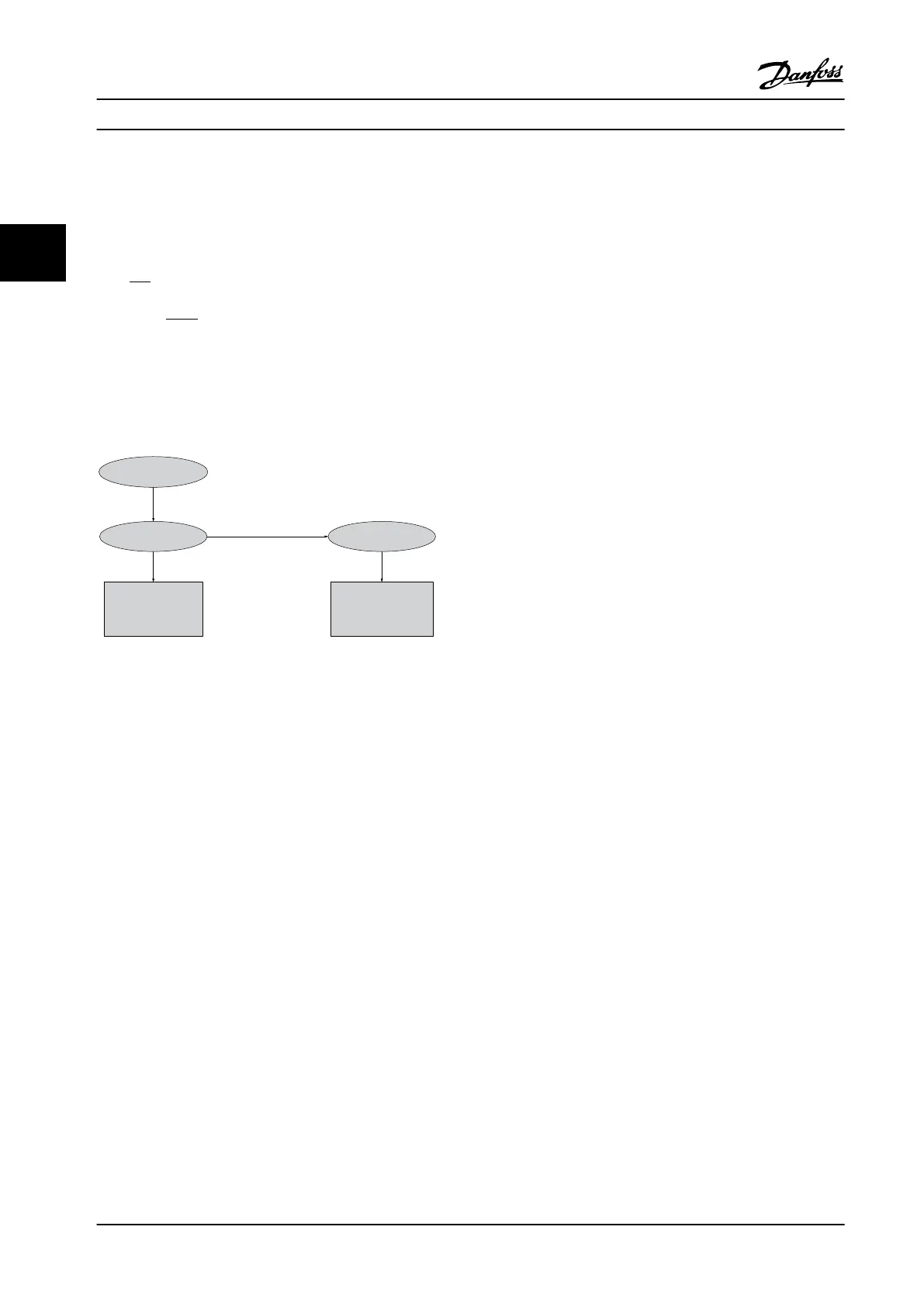
The negative eect of harmonics is two-fold
•
Harmonic currents contribute to system losses (in
cabling, transformer).
•
Harmonic voltage distortion causes disturbance
to other loads and increase losses in other loads.
Non-linear
Current Voltage
System
Impedance
Disturbance to
other users
Contribution to
system losses
130BB541.10
Figure 3.5 Negative Eects of Harmonics
3.2.7.5 Harmonic Limitation Standards and
Requirements
The requirements for harmonic limitation can be:
•
Application-specic requirements.
•
Standards that must be observed.
The application-specic requirements are related to a
specic installation where there are technical reasons for
limiting the harmonics.
Example
A 250 kVA transformer with two 110 kW (150 hp) motors
connected is sucient if one of the motors is connected
directly online and the other is supplied through an
adjustable frequency drive. However, the transformer is
undersized if both motors are supplied by the adjustable
frequency drive. Using additional means of harmonic
reduction within the installation or selecting low harmonic
drive variants makes it possible for both motors to run
with adjustable frequency drives.
There are various harmonic mitigation standards,
regulations, and recommendations. Dierent standards
apply in dierent geographical areas and industries. The
following standards are the most common:
•
IEC61000-3-2
•
IEC61000-3-12
•
IEC61000-3-4
•
IEEE 519
•
G5/4
See the AHF 005/010 Design Guide for specic details on
each standard.
In Europe, the maximum THVD is 8% if the plant is
connected via the public grid. If the plant has its own
transformer, the limit is 10% THVD. The VLT
®
AQUA Drive is
designed to withstand 10% THVD.
3.2.7.6
Harmonic Mitigation
In cases where additional harmonic suppression is
required, Danfoss oers a wide range of mitigation
equipment. These are:
•
12-pulse drives
•
AHF lters
•
Low Harmonic Drives
•
Active Filters
The choice of the right solution depends on several
factors:
•
The grid (background distortion, line power
unbalance, resonance and type of supply
(transformer/generator).
•
Application (load prole, number of loads and
load size).
•
Local/national requirements/regulations (IEEE519,
IEC, G5/4, etc.).
•
Total cost of ownership (initial cost, eciency,
maintenance, etc.).
Always consider harmonic mitigation if the transformer
load has a non-linear contribution of 40% or more.
Danfoss oers tools for calculation of harmonics, see
chapter 2.8.2 PC Software.
3.2.8
Ground Leakage Current
Follow national and local codes regarding protective
grounding of equipment where leakage current exceeds
3.5 mA.
Adjustable frequency drive technology implies high
frequency switching at high power. This generates a
leakage current in the ground connection.
System Integration
VLT
®
AQUA Drive FC 202
52 Danfoss A/S © 09/2014 All rights reserved. MG20N622
33

 Loading...


