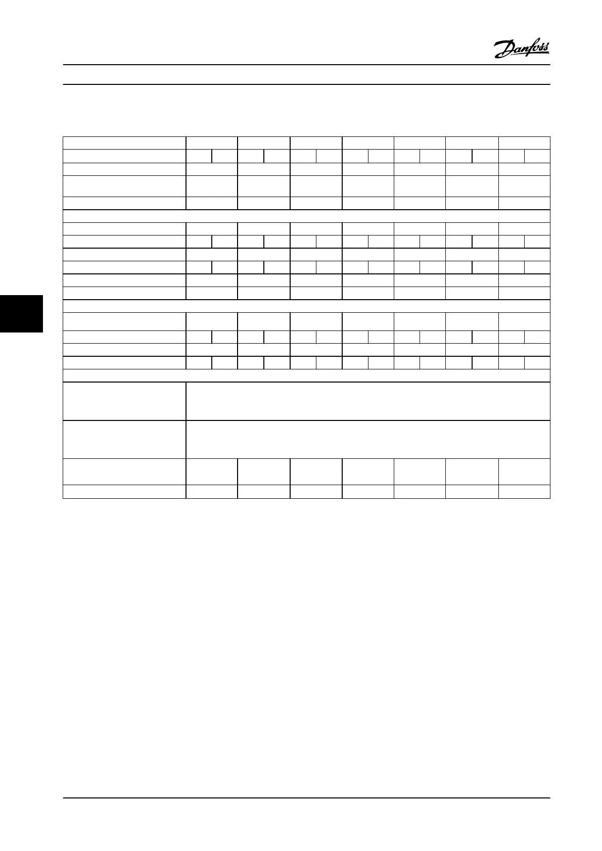
7.1.6 Line Power Supply 3x525–690 V AC
Type designation P1K1 P1K5 P2K2 P3K0 P4K0 P5K5 P7K5
High/normal overload
1)
HO NO HO NO HO NO HO NO HO NO HO NO HO NO
Typical shaft output [kW] 1.1 1.5 2.2 3.0 4.0 5.5 7.5
Typical shaft output [hp] 1.5 2 3 4 5 7.5 10
Protection rating IP20/Chassis A3 A3 A3 A3 A3 A3 A3
Output current
Continuous (3x525–550 V) [A] 2.1 2.7 3.9 4.9 6.1 9.0 11.0
Intermittent (3x525–550 V) [A] 3.2 2.3 4.1 3.0 5.9 4.3 7.4 5.4 9.2 6.7 13.5 9.9 16.5 12.1
Continuous (3x551–690 V) [A] 1.6 2.2 3.2 4.5 5.5 7.5 10.0
Intermittent (3x551–690 V) [A] 2.4 1.8 3.3 2.4 4.8 3.5 6.8 5.0 8.3 6.1 11.3 8.3 15.0 11.0
Continuous kVA at 525 V [kVA] 1.9 2.5 3.5 4.5 5.5 8.2 10.0
Continuous kVA at 690 V [kVA] 1.9 2.6 3.8 5.4 6.6 9.0 12.0
Maximum input current
Continuous (3x525–550 V) [A] 1.9 2.4 3.5 4.4 5.5 8.1 9.9
Intermittent (3x525–550 V) [A] 2.9 2.1 3.6 2.6 5.3 3.9 6.6 4.8 8.3 6.1 12.2 8.9 14.9 10.9
Continuous (3x551–690 V) [A] 1.4 2.0 2.9 4.0 4.9 6.7 9.0
Intermittent (3x551–690 V) [A] 2.1 1.5 3.0 2.2 4.4 3.2 6.0 4.4 7.4 5.4 10.1 7.4 13.5 9.9
Additional specications
Maximum cable cross-section
2)
for
line power, motor, brake, and
load sharing [mm
2
] ([AWG])
4, 4, 4
(12, 12, 12)
(minimum 0.2 (24))
Maximum cable cross-section
2)
for
line power disconnect
[mm
2
] ([AWG])
6, 4, 4
(10, 12, 12)
Estimated power loss
3)
at rated maximum load [W]
4)
44 60 88 120 160 220 300
Eciency
5)
0.96 0.96 0.96 0.96 0.96 0.96 0.96
Table 7.15 A3 Enclosure, Line Power Supply 3x525–690 V AC IP20/Protected Chassis, P1K1–P7K5
Specications
VLT
®
AQUA Drive FC 202
162 Danfoss A/S © 09/2014 All rights reserved. MG20N622
77

 Loading...


