2.3.5 Load Sharing
Units with the built-in load sharing option contain
terminals (+) 89 DC and (–) 88 DC. Within the adjustable
frequency drive, these terminals connect to the DC bus in
front of the DC link reactor and bus capacitors.
For more information, contact Danfoss.
The load sharing terminals can connect in two
dierent
congurations.
1. In the rst method, the terminals tie the DC bus
circuits of multiple adjustable frequency drives
together. This allows a unit that is in a
regenerative mode to share its excess bus voltage
with another unit that is running a motor. Load
sharing in this manner can reduce the need for
external dynamic brake resistors, while also
saving energy. The number of units that can be
connected in this way is innite, as long as each
unit has the same voltage rating. In addition,
depending on the size and number of units, it
may be necessary to install DC reactors and DC
fuses in the DC link connections, and AC reactors
on line power. Attempting such a conguration
requires specic considerations. Contact Danfoss
for assistance.
2. In the second method, the adjustable frequency
drive is powered exclusively from a DC source.
This requires:
2a A DC source.
2b A means to soft charge the DC bus at
power-up.
Again, attempting such a conguration requires
specic considerations. Contact Danfoss for
assistance.
2.4 Control Structures
2.4.1 Control Structure Open-loop
When operating in open-loop mode, the adjustable
frequency drive responds to input commands manually via
the LCP keys or remotely via the analog/digital inputs or
serial bus.
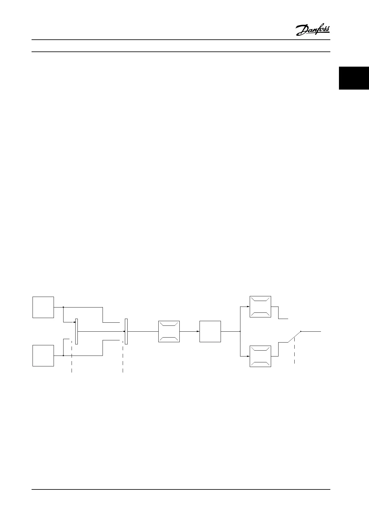
In the conguration shown in Figure 2.11, the adjustable
frequency drive operates in open-loop mode. It receives
input from either the LCP (Hand mode) or via a remote
signal (Auto mode). The signal (speed reference) is received
and conditioned with programmed minimum and
maximum motor speed limits (in RPM and Hz), ramp-up
and ramp-down times, and the motor rotation direction.
The reference is then passed on to control the motor.
130BB153.10
100%
0%
-100%
100%
P 3-13
Reference
site
Local
reference
scaled to
RPM or Hz
Auto mode
Hand mode
LCP Hand on,
o and auto
on keys
Linked to hand/auto
Local
Remote
Reference
Ramp
P 4-10
Motor speed
direction
To motor
control
Reference
handling
Remote
reference
P 4-13
Motor speed
high limit [RPM]
P 4-14
Motor speed
high limit [Hz]
P 4-11
Motor speed
low limit [RPM]
P 4-12
Motor speed
low limit [Hz]
P 3-4* Ramp 1
P 3-5* Ramp 2
Figure 2.11 Open-loop Mode Block Diagram
Product Overview Design Guide
MG20N622 Danfoss A/S © 09/2014 All rights reserved. 21
2 2

 Loading...


