The adjustable frequency drive manages various motor
control principles such as U/f special motor mode and VVC
+
. Short-circuit behavior of the adjustable frequency drive
depends on the three current transducers in the motor
phases.
Inrush
R inr
Load sharing -
Load sharing +
LC Filter -
(5A)
LC Filter +
(5A)
Brake
Resistor
130BA193.14
M
L2 92
L1 91
L3 93
89(+)
88(-)
R+
82
R-
81
U 96
V 97
W 98
P 14-50 R Filter
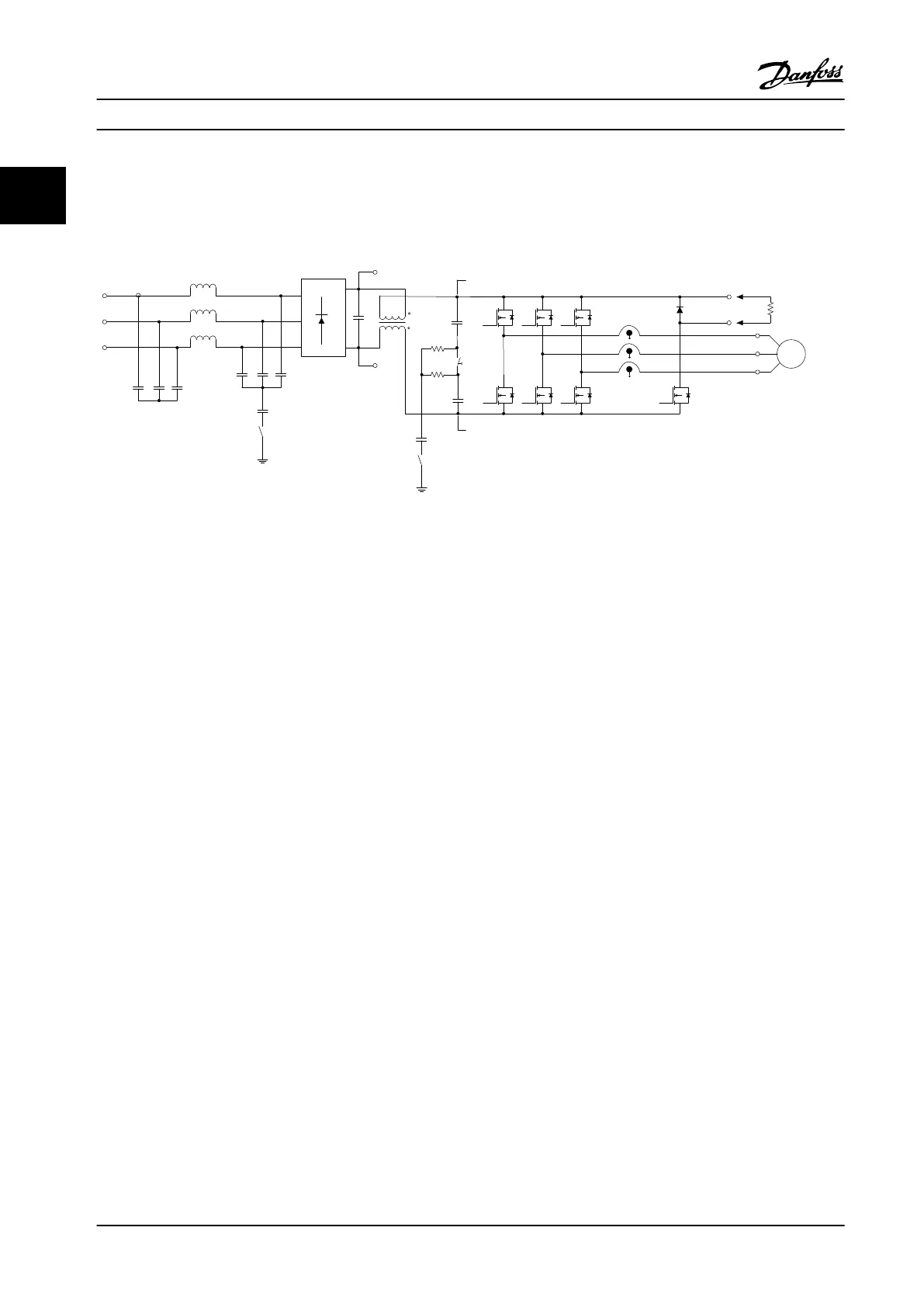
Figure 2.10 Adjustable Frequency Drive Structure
2.3 Sequence of Operation
2.3.1 Rectier Section
When power is applied to the adjustable frequency drive, it
enters through the line power terminals (L1, L2, and L3)
and on to the disconnect and/or RFI lter option,
depending on the unit conguration.
2.3.2 Intermediate Section
Following the rectier section, voltage passes to the
intermediate section. A sine-wave lter circuit consisting of
the DC bus inductor and the DC bus capacitor bank
smoothes the rectied voltage.
The DC bus inductor provides series impedance to
changing current. This aids the ltering process while
reducing harmonic distortion to the input AC current
waveform normally inherent in rectier circuits.
2.3.3
Inverter Section
In the inverter section, once a run command and speed
reference are present, the IGBTs begin switching to create
the output waveform. This waveform, as generated by the
Danfoss VVC
+
PWM principle at the control card, provides
optimal performance and minimal losses in the motor.
2.3.4
Brake Option
For adjustable frequency drives equipped with the
dynamic brake option, a brake IGBT along with terminals
81(R-) and 82(R+) are included for connecting an external
brake resistor.
The function of the brake IGBT is to limit the voltage in the
intermediate circuit whenever the maximum voltage limit
is exceeded. It does this by switching the externally
mounted resistor across the DC bus to remove excess DC
voltage present on the bus capacitors.
External brake resistor placement has the advantages of
selecting the resistor based on application need,
dissipating the energy outside of the control panel, and
protecting the drive from overheating if the brake resistor
is overloaded.
The brake IGBT gate signal originates on the control card
and is delivered to the brake IGBT via the power card and
gate drive card. Additionally, the power and control cards
monitor the brake IGBT and brake resistor connection for
short circuits and overloads. For pre-fuse
specications,
refer to chapter 7.1 Electrical Data. See also
chapter 7.7 Fuses and Circuit Breakers.
Product Overview
VLT
®
AQUA Drive FC 202
20 Danfoss A/S © 09/2014 All rights reserved. MG20N622
22

 Loading...


