2 Product Overview
2.1 Introduction
This chapter provides an overview of the adjustable
frequency drive’s primary assemblies and circuitry. It
describes the internal electrical and signal processing
functions. A description of the internal control structure is
also included.
Also described are automated and optional adjustable
frequency drive functions available for designing robust
operating systems with sophisticated control and status
reporting performance.
2.1.1
Product Dedication to Water and
Wastewater Applications
The VLT
®
AQUA Drive FC 202 is designed for water and
wastewater applications. The integrated SmartStart wizard
and the quick menu Water and Pumps guide the user
through the commissioning process. The range of standard
and optional features includes:
•
Cascade control
•
Dry-run detection
•
End of curve detection
•
Motor alternation
•
Deragging
•
Initial and
nal ramp
•
Check valve ramp
•
STO
•
Low-ow detection
•
Pre-lube
•
Flow conrmation
•
Pipe ll mode
•
Sleep mode
•
Real time clock
•
Password protection
•
Overload protection
•
Smart logic control
•
Minimum speed monitor
•
Free programmable texts for information,
warnings and alerts
2.1.2
Energy Savings
Compared to alternative control systems and technologies,
an adjustable frequency drive is the optimum energy
control system for controlling fan and pump systems.
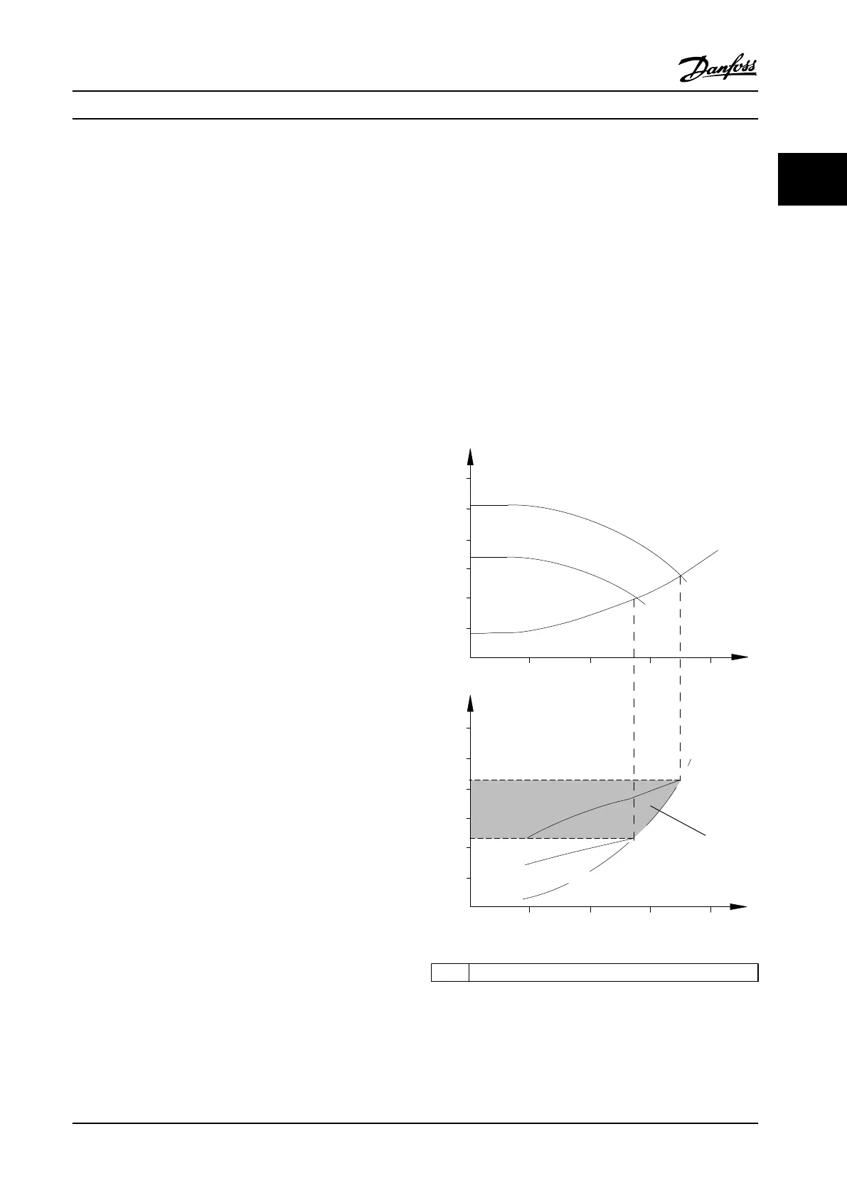
By using an adjustable frequency drive to control the ow,
a pump speed reduction of 20% leads to energy savings of
about 50% in typical applications.
Figure 2.1 shows an example of the achievable energy
reduction.
130BD889.10
60
50
40
30
20
10
H
s
0 100 200 300 400
(mwg)
1350rpm
1650rpm
0
10
20
30
(kW)
40
50
60
200100 300
(m
3
/h)
(
m
3
/h)
400
1350rpm
1650rpm
P
shaft
1
1 Energy saving
Figure 2.1 Example: Energy Saving
Product Overview Design Guide
MG20N622 Danfoss A/S © 09/2014 All rights reserved. 15
2 2

 Loading...


