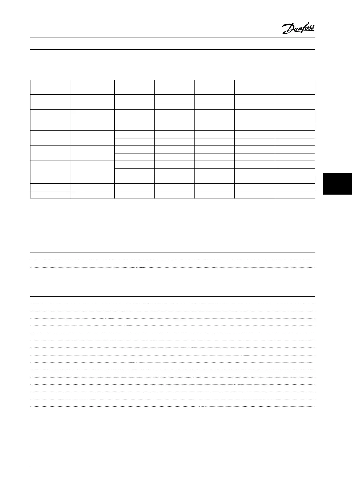
7.5.1 Cable Lengths for Multiple Parallel Motor Connections
Enclosure sizes Power Size [kW
(hp)]
Voltage [V] 1 cable [m (ft)] 2 cables [m (ft)] 3 cables [m (ft)] 4 cables [m (ft)]
A1, A2, A4, A5 0.37–0.75 (0.5–1)
400 150 (492) 45 (147) 8 (26) 6 (20)
500 150 (492) 7 (23) 4 (13) 3 (10)
A2, A4, A5 1.1–1.5 (1.5–2)
400 150 (492) 45 (147) 20 (65) 8 (26)
500 150 (492) 45 (147) 5 (16) 4 (13)
A2, A4, A5 2.2–4 (3–5)
400 150 (492) 45 (147) 20 (65) 11 (36)
500 150 (492) 45 (147) 20 (65) 6 (20)
A3, A4, A5 5.5–7.5 (7.5–10)
400 150 (492) 45 (147) 20 (65) 11 (36)
500 150 (492) 45 (147) 20 (65) 11 (36)
B1, B2, B3, B4,
C1, C2, C3, C4
11–75 (15–100)
400 150 (147) 75 (246) 50 (164) 37 (123)
500 150 (147) 75 (246) 50 (164) 37 (123)
A3 1.1–7.5 (1.5–10) 525–690 100 (328) 50 (164) 33 (108) 25 (82)
B4 11–30 (15–40) 525–690 150 (492) 75 (246) 50 (164) 37 (123)
C3 37–45 (50–60) 525–690 150 (492) 75 (246) 50 (164) 37 (123)
Table 7.18 Maximum Cable Length for Each Parallel Cable
1)
1) For more information, refer to chapter 3.4.6 Connection of Multiple
Motors.
7.6 Control Input/Output and Control Data
Control card, RS485 serial communication
Terminal number 68 (P,TX+, RX+), 69 (N,TX-, RX-)
Terminal number 61 common for terminals 68 and 69
The RS485 serial communication circuit is functionally separated from other central circuits and galvanically isolated from the
supply voltage (PELV).
Analog inputs
Number of analog inputs 2
Terminal number 53, 54
Modes voltage or current
Mode select switches S201 and S202
Voltage mode switch S201/S202 = OFF (U)
Voltage level 0–10 V (scaleable)
Input resistance, R
i
approx. 10 kΩ
Maximum voltage ±20 V
Current mode switch S201/S202=On (I)
Current level 0/4-20 mA (scaleable)
Input resistance, R
i
approx. 200 Ω
Maximum current 30 mA
Resolution for analog inputs 10 bit (+ sign)
Accuracy of analog inputs maximum error 0.5% of full scale
Bandwidth 200 Hz
The analog inputs are galvanically isolated from the supply voltage (PELV) and other high-voltage terminals.
Specications Design Guide
MG20N622 Danfoss A/S © 09/2014 All rights reserved. 167
7 7

 Loading...


