3.4 Motor Integration
3.4.1 Motor Selection Considerations
The adjustable frequency drive can induce electrical stress
on a motor. Consider, therefore, the following eects on
the motor when matching motor with adjustable
frequency drive:
•
Insulation stress
•
Bearing stress
•
Thermal stress
3.4.2
Sine-wave and dU/dt Filters
Output lters provide benets to some motors to reduce
electrical stress and allow for longer cable length. Output
options include sine-wave lters (also called LC lters) and
dU/dt lters. The dU/dt lters reduce the sharp rise rate of
the pulse. Sine-wave lters smooth the voltage pulses to
convert them into a nearly sinusoidal output voltage. With
some adjustable frequency drives, sine-wave
lters comply
with EN 61800-3 RFI category C2 for non-shielded motor
cables, see chapter 3.7.5 Sine-wave Filters.
For more information on sine-wave and dU/dt lter
options, refer to chapter 3.7.5 Sine-wave Filters and
chapter 3.7.6 dU/dt Filters.
For more information on sine-wave and dU/dt lter
ordering numbers, refer to and chapter 6.2.9 dU/dt Filters.
3.4.3
Proper Motor Grounding
Proper grounding of the motor is imperative for personal
safety and to meet EMC electrical requirements for low
voltage equipment. Proper grounding is necessary for the
eective use of shielding and lters. Design details must
be veried for proper EMC implementation.
3.4.4
Motor Cables
Motor cable recommendations and specications are
provided in chapter 7.5 Cable Specications.
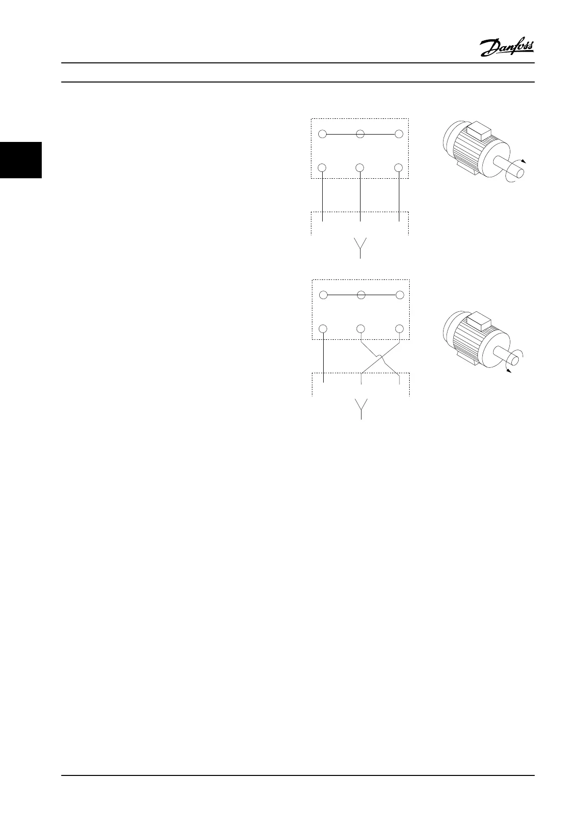
All types of three-phase asynchronous standard motors can
be used with an adjustable frequency drive unit. The
factory setting is for clockwise rotation with the adjustable
frequency drive output connected as follows:
175HA036.11
U
1
V
1
W
1
96 97 98
FC
Motor
U
2
V
2
W
2
U
1
V
1
W
1
96 97 98
FC
Motor
U
2
V
2
W
2
Figure 3.10 Terminal Connection for Clockwise and Counter-
clockwise Rotation
Change the direction of rotation by switching two phases
in the motor cable or by changing the setting of
4-10 Motor Speed Direction.
3.4.5
Motor Cable Shielding
Adjustable frequency drives generate steep-edged pulses
on their outputs. These pulses contain high-frequency
components (extending into the gigahertz range), which
cause undesirable radiation from the motor cable. Shielded
motor cables reduce this radiation.
The purposes of shielding are to:
•
Reduce the magnitude of radiated interference.
•
Improve the interference immunity of individual
devices.
The shield captures the high-frequency components and
conducts them back to the interference source, in this case
the adjustable frequency drive. Shielded motor cables also
provide immunity to interference from nearby external
sources.
System Integration
VLT
®
AQUA Drive FC 202
58 Danfoss A/S © 09/2014 All rights reserved. MG20N622
33

 Loading...


