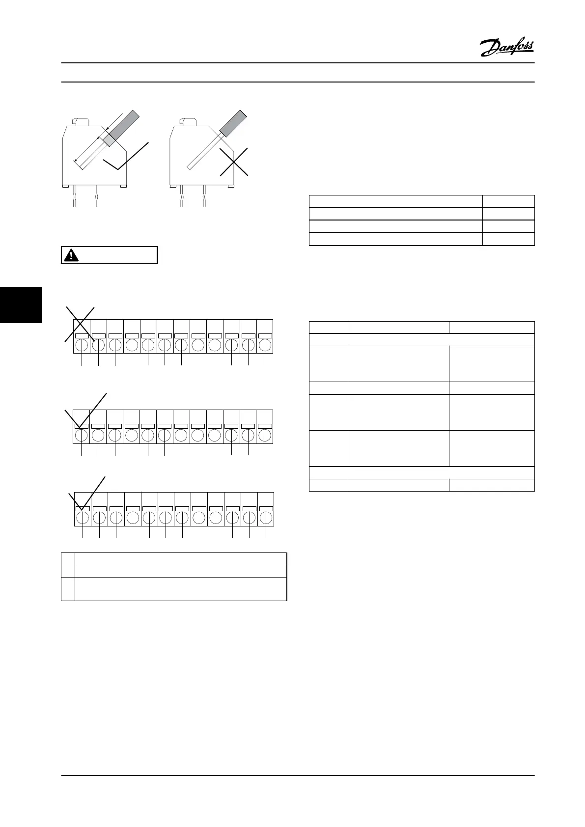
Figure 7.15 Mounting of Cables
WARNING
Do not combine low voltage parts and PELV systems (see
Figure 7.16.
1 1 1
1 102 3 4 5 6 7 8 9 1211
2 2 3
1 1 1
1 102 3 4 5 6 7 8 9 1211
3 3 3
1 1 1
1 102 3 4 5 6 7 8 9 1211
2 2
2
130BA176.11
1 NC
2 Live part
3 PELV
Figure 7.16 Incorrect and Correct Relay Wiring
7.11.7
VLT
®
Advanced Cascade Controller
MCO 102
The VLT advanced cascade control card MCO 102 option is
exclusively intended for use in option slot C1. The
mounting position of C1 options is shown in Figure 7.17.
Max terminal load (AC) 240 V AC 2 A
Max terminal load (DC) 24 V DC 1 A
Min terminal load (DC) 5 V 10 mA
Max switching rate at rated load/minimum load
6 min
-1
/20 s
-1
Table 7.62 Electrical Data, MCO 102
Tools required
Some items are needed for the installation of a C option
mounting kit (depending on the enclosure):
Type Description Ordering number
Options
MCF 105 Mounting Kit frame size A2
and A3 (40 mm (1.57 in) for
one C Option)
130B7530
MCF 105 Mounting Kit Frame size A5 130B7532
MCF 105 Mounting Kit Frame size B,
C, D, E, F1 and F3 (Except
B3)
130B7533
MCF 105 Mounting Kit frame size B3
(40 mm (1.57 in) for one C
Option)
130B1413
Accessory bag
MCO 102 Accessory Bag 130B0152
Table 7.63 Ordering Numbers for Mounting Kits and Accessory
Bag
Specications
VLT
®
AQUA Drive FC 202
192 Danfoss A/S © 09/2014 All rights reserved. MG20N622
77

 Loading...


