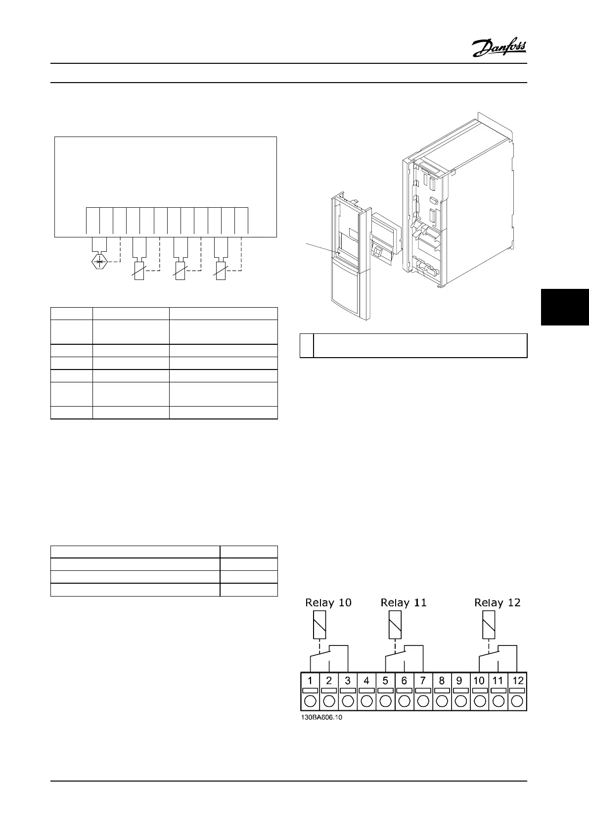
7.11.5.2 Electrical Wiring
MCB 114
Sensor Input Option B
SW. ver. xx.xx Code No. 130B1272
4-20mA
2 or 3
wire
2 or 3
wire
2 or 3
wire
2 or 3
wire
130BB326.10
Terminal Name Function
1 VDD 24 V DC to supply 4–20 mA
sensor
2 I in 4–20 mA input
3 GND Analog input GND
4, 7, 10 Temp 1, 2, 3 Temperature input
5, 8, 11 Wire 1, 2, 3 Third wire input if three wire
sensors are used
6, 9, 12 GND Temperature input GND
Figure 7.12 MCB 114 Electrical Wiring
7.11.6
VLT
®
Extended Cascade Controller
MCO 101
The MCO 101 option includes three change-over contacts
and can be inserted into option slot B.
Max terminal load (AC)
240 V AC 2 A
Max terminal load (DC) 24 V DC 1 A
Min terminal load (DC) 5 V 10 mA
Max switching rate at rated load/min load
6 min
-1
/20 s
-1
Table 7.61 MCO 101 Electrical Data
1
Dismount MCO 101 option to access RS485 termination
(S801) or current/voltage switches (S201, S202)
Figure 7.13 Mounting of B Option
How to add the MCO 101 option:
1. Disconnect power to the adjustable frequency
drive.
2. Disconnect power to the live part connections on
relay terminals.
3. Remove the LCP, the terminal cover and the
cradle from the FC 202.
4. Fit the MCO 101 option in slot B.
5. Connect the control cables and relieve the cables
by the enclosed cable strips.
6. Fit the extended cradle and terminal cover.
7. Remount the LCP.
8. Connect power to the adjustable frequency drive.
Figure 7.14 Usage of Connections
Specications Design Guide
MG20N622 Danfoss A/S © 09/2014 All rights reserved. 191
7 7

 Loading...


