NOTICE!
Adjustable frequency drives with the MCB 112 option
have PTB-certied motor thermistor sensor monitoring
capability for potentially explosive atmospheres.
Shielded motor cables are not necessary when
adjustable frequency drives are operated with sine-wave
output lters.
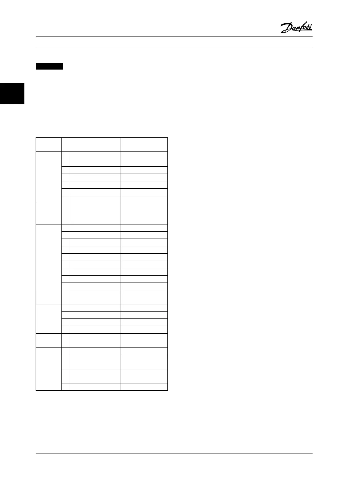
3.1.8 IP Rating Denitions
Against penetration by
solid foreign objects
Against access to
hazardous parts by
First digit
0 (not protected) (not protected)
1
≥50 mm diameter
Back of hand
2 12.5 mm diameter Finger
3 2.5 mm diameter Tool
4
≥1.0 mm diameter
Wire
5 Dust protected Wire
6 Dust-tight Wire
Against water
penetration with
harmful eect
Second
digit
0 (not protected)
1 Drops falling vertically
2 Drops at 15° angle
3 Spraying water
4 Splashing water
5 Water jets
6 Powerful water jets
7 Temporary immersion
8 Long-term immersion
Additional information
specically for
First letter
A Back of hand
B Finger
C Tool
D Wire
Additional information
specically for
Additional
letter
H High-voltage device
M Device moving during
water test
S Device stationary during
water test
W Weather conditions
Table 3.3 IEC 60529 Denitions for IP Ratings
3.1.8.1
Cabinet Options and Ratings
Danfoss adjustable frequency drives are available with
three dierent protection ratings:
•
IP00 or IP20 for cabinet installation.
•
IP54 or IP55 for local mounting.
•
IP66 for critical ambient conditions such as
extremely high (air) humidity or high concen-
trations of dust or aggressive gases.
3.1.9 Radio Frequency Interference
The main objective in practice is to obtain systems that
operate stably without radio frequency interference
between components. To achieve a high level of immunity,
it is recommended to use adjustable frequency drives with
high-quality RFI lters.
Use Category C1 lters specied in the EN 61800-3 which
conform to the Class B limits of the general standard EN
55011.
Place warning notices on the adjustable frequency drive if
RFI lters do not correspond to Category C1 (Category C2
or lower). The responsibility for proper labeling rests with
the operator.
In practice, there are two approaches to RFI
lters:
•
Built into the equipment
-
Built-in lters take up space in the
cabinet but eliminate additional costs
for tting, wiring, and material. However,
the most important advantage is the
perfect EMC conformance and cabling
of integrated lters.
•
External options
-
Optional external RFI lters that are
installed on the input of the adjustable
frequency drive cause a voltage drop. In
practice, this means that the full AC line
voltage is not present at the adjustable
frequency drive input and a higher-rated
drive may be necessary. The maximum
length of the motor cable for
compliance with EMC limits ranges from
1–50 m (3.3–164 ft). Costs are incurred
for material, cabling, and assembly. EMC
conformance is not tested.
System Integration
VLT
®
AQUA Drive FC 202
42 Danfoss A/S © 09/2014 All rights reserved. MG20N622
33

 Loading...


