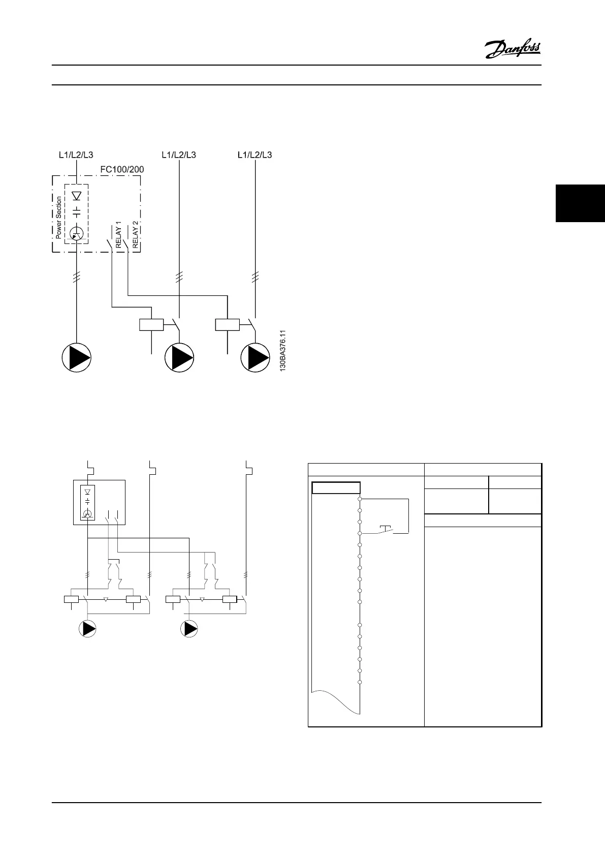
4.3.6 Fixed Variable-speed Pump Wiring
Diagram
Figure 4.12 Fixed Variable-speed Pump Wiring Diagram
4.3.7
Lead Pump Alternation Wiring
Diagram
130BA377.13
L1/L2/L3
FC
L1/L2/L3
L1/L2/L3
k3
k2
k3
k1
K2
K1
K1
K1
K4
K3
K4
K3
R1
R2
Figure 4.13 Lead Pump Alternation Wiring Diagram
Every pump must be connected to two contactors (K1/K2
and K3/K4) with a mechanical interlock. Thermal relays or
other motor protection devices must be applied according
to local regulation and/or individual demands.
•
Relay 1 (R1) and Relay 2 (R2) are the built-in
relays in the adjustable frequency drive.
•
When all relays are de-energized, the rst built-in
relay that is energized cuts in the contactor
corresponding to the pump controlled by the
relay. For example, Relay 1 cuts in contactor K1,
which becomes the lead pump.
•
K1 blocks for K2 via the mechanical interlock,
preventing line power from being connected to
the output of the adjustable frequency drive (via
K1).
•
Auxiliary break contact on K1 prevents K3 from
cutting in.
•
Relay 2 controls contactor K4 for on/o control of
the xed-speed pump.
•
At alternation, both relays de-energize and now
Relay 2 is energized as the rst relay.
For a detailed description of commissioning for mixed-
pump and master/slave applications, refer to VLT
®
Cascade
Controller Options MCO 101/102 Instruction Manual.
4.3.8
External Alarm Reset
Parameters
FC
+24 V
+24 V
D IN
D IN
D IN
COM
D IN
D IN
D IN
D IN
+10
A IN
A IN
COM
A OUT
COM
12
13
18
19
20
27
29
32
33
37
50
53
54
55
42
39
130BB682.10
Function Setting
5-11 Terminal 19
Digital Input
[1] Reset
* = Default value
Notes/comments:
D IN 37 is an option.
Table 4.6 External Alarm Reset
Application Examples
Design Guide
MG20N622 Danfoss A/S © 09/2014 All rights reserved. 111
4 4

 Loading...


