8.2 Motor Connection Drawings
Motor connection
This collection of drawings is intended to aid planning for
access in the design phase.
Refer to the instruction manual for installation procedures
including:
•
Safety requirements.
•
Step-by-step installation procedures.
•
Terminal descriptions.
•
Alternative
congurations.
•
Additional drawings.
Termi
nal
numb
er
96 97 98 99
U V W
PE
1)
Motor voltage 0–100% of AC line
voltage.
3 wires out of motor
U1 V1 W1
PE
1)
Delta-connected
W2 U2 V2 6 wires out of motor
U1 V1 W1
PE
1)
Star-connected U2, V2, W2
U2, V2 and W2 to be intercon-
nected separately.
Table 8.1 Terminal Descriptions
1) Protected Ground Connection
U
1
V
1
W
1
175ZA114.11
96 97 98
96 97 98
FC
FC
Motor
Motor
U
2
V
2
W
2
U
1
V
1
W
1
U
2
V
2
W
2
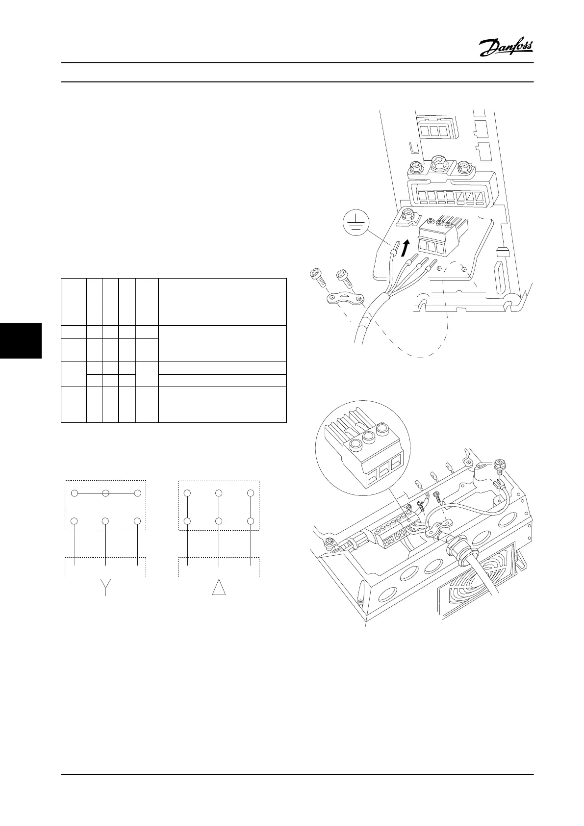
Figure 8.10 Star and Delta Connections
All types of three-phase asynchronous standard motors can
be connected to the adjustable frequency drive. Normally,
small motors are star-connected (230/400 V, Y). Large
motors are normally delta-connected (400/690 V, Δ). Refer
to the motor nameplate for correct connection mode and
voltage.
MOTOR
MOTOR
U V W
99
130BT302.12
Figure 8.11 Motor Connection for Enclosures A1, A2 and A3
Figure 8.12 Motor Connection for Enclosures A4/A5
Appendix - Selected Drawing...
VLT
®
AQUA Drive FC 202
198 Danfoss A/S © 09/2014 All rights reserved. MG20N622
88

 Loading...


