4.3.3 Pump Staging with Lead Pump
Alternation
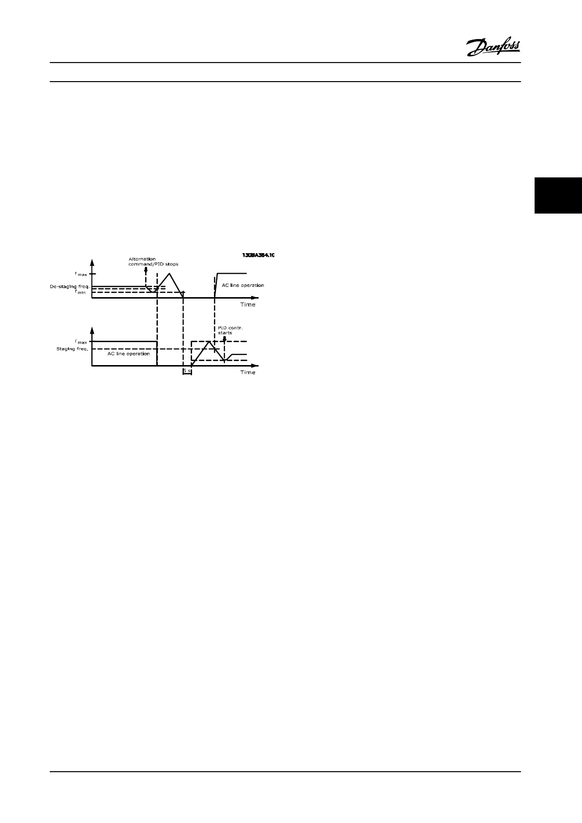
With lead pump alternation enabled, a maximum of two
pumps are controlled. At an alternation command, the PID
stops, the lead pump ramps to minimum frequency (f
min
)
and, after a delay, it ramps to maximum frequency (f
max
).
When the speed of the lead pump reaches the de-staging
frequency, the xed-speed pump is cut out (de-staged).
The lead pump continues to ramp up and then ramps
down to a stop and the two relays are cut out.
Figure 4.10 Lead Pump Alternation
After a time delay, the relay for the xed-speed pump cuts
in (staged) and this pump becomes the new lead pump.
The new lead pump ramps up to maximum speed and
then down to minimum speed. When ramping down and
reaching the staging frequency, the old lead pump is now
cut in (staged) on line power as the new xed-speed
pump.
If the lead pump has been running at minimum frequency
(f
min
) for a programmed amount of time, with a xed-
speed pump running, the lead pump contributes little to
the system. When programmed value of the timer expires,
the lead pump is removed, avoiding water heating
problems.
4.3.4
System Status and Operation
If the lead pump goes into sleep mode, the function is
displayed on the LCP. It is possible to alternate the lead
pump into a sleep mode condition.
When the cascade controller is enabled, the operation
status for each pump and the cascade controller is
displayed on the LCP. Information displayed includes:
•
Pumps status is a readout of the status for the
relays assigned to each pump. The display shows
pumps that are disabled, o, running on the
adjustable frequency drive, or running on the line
power/motor starter.
•
Cascade status is a readout of the status for the
cascade controller. The display shows that the
cascade controller is disabled, all pumps are o,
and emergency has stopped all pumps, all pumps
are running, xed-speed pumps are being
staged/de-staged and lead pump alternation is
occurring.
•
De-stage at no-ow ensures that all xed-speed
pumps are stopped individually until the no-ow
status disappears.
Application Examples Design Guide
MG20N622 Danfoss A/S © 09/2014 All rights reserved. 109
4 4

 Loading...


