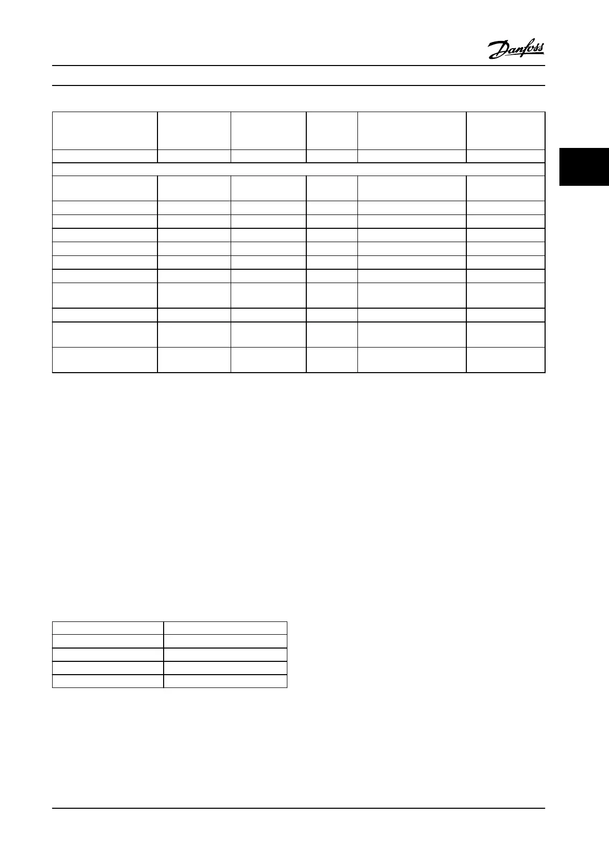
Basic standard
Burst
2)
IEC 61000-4-42)
Surge
2)
IEC 61000-4-5
ESD
2)
IEC
61000-4-2
Radiated electromagnetic
eld
IEC 61000-4-3
RF common
mode voltage
IEC 61000-4-6
Acceptance criterion B B B A A
Voltage range: 200–240 V, 380–500 V, 525–600 V, 525–690 V
Line
4 kV CM
2 kV/2 Ω DM
4 kV/12 Ω CM
— —
10 V
RMS
Motor
4 kV CM
4 kV/2 Ω
1)
— —
10 V
RMS
Brake 4 kV CM
4 kV/2 Ω
1)
— —
10 V
RMS
Load sharing 4 kV CM
4 kV/2 Ω
1)
— —
10 V
RMS
Control wires
2 kV CM
2 kV/2 Ω
1)
— —
10 V
RMS
Standard bus 2 kV CM
2 kV/2 Ω
1)
— —
10 V
RMS
Relay wires 2 kV CM
2 kV/2 Ω
1)
— —
10 V
RMS
Application and serial
communication options
2 kV CM
2 kV/2 Ω
1)
— —
10 V
RMS
LCP cable
2 kV CM
2 kV/2 Ω
1)
— —
10 V
RMS
External 24 V DC
2 V CM
0.5 kV/2 Ω DM
1 kV/12 Ω CM
— —
10 V
RMS
Enclosure
— —
8 kV AD
6 kV CD
10 V/m —
Table 3.7 EMC Immunity Form
1) Injection on cable shield
2) Values typically obtained by testing
3.2.5
Motor Insulation
Modern motors for use with adjustable frequency drives
have a high degree of insulation to account for new
generation high-eciency IGBTs with high dU/dt. For
retrot in old motors, conrm the motor insulation or
mitigate with dU/dt lter or, if necessary, a sine-wave lter.
For motor cable lengths ≤ the maximum cable length
listed in chapter 7.5 Cable Specications, the motor
insulation ratings listed in Table 3.8 are recommended. If a
motor has lower insulation rating, it is recommended to
use a dU/dt or sine-wave lter.
Nominal AC line voltage [V] Motor insulation [V]
U
N
≤420
Standard U
LL
=1300
420 V< U
N
≤ 500 Reinforced U
LL
=1600
500 V< U
N
≤ 600 Reinforced U
LL
=1800
600 V< U
N
≤ 690 Reinforced U
LL
=2000
Table 3.8 Motor Insulation
3.2.6
Motor Bearing Currents
To minimize bearing and shaft currents, ground the
following to the driven machine:
•
Adjustable frequency drive
•
Motor
•
Driven machine
Standard mitigation strategies
1. Use an insulated bearing.
2. Apply rigorous installation procedures:
2a Ensure that the motor and load motor
are aligned.
2b Strictly follow the EMC Installation
guideline.
2c Reinforce the PE so the high frequency
impedance is lower in the PE than the
input power leads.
2d Provide a good high frequency
connection between the motor and the
adjustable frequency drive, for instance,
by a shielded cable which has a 360°
connection in the motor and the
adjustable frequency drive.
System Integration Design Guide
MG20N622 Danfoss A/S © 09/2014 All rights reserved. 49
3 3

 Loading...


