2e Make sure that the impedance from
adjustable frequency drive to building
ground is lower that the grounding
impedance of the machine. This can be
dicult for pumps.
2f Make a direct ground connection
between the motor and load motor.
3. Lower the IGBT switching frequency.
4. Modify the inverter waveform, 60° AVM vs.
SFAVM.
5. Install a shaft grounding system or use an
isolating coupling.
6. Apply conductive lubrication.
7. Use minimum speed settings if possible.
8. Try to ensure the line voltage is balanced to
ground. This can be dicult for IT, TT, TN-CS or
Grounded leg systems.
9. Use a dU/dt or sine-wave lter.
3.2.7
Harmonics
Electrical devices with diode rectiers, such as uorescent
lights, computers, copiers, fax machines, various laboratory
equipment and telecommunications systems, can add
harmonic distortion to a line power supply. Adjustable
frequency drives use a diode bridge input, which can also
contribute to harmonic distortion.
The adjustable frequency drive does not draw current
uniformly from the power line. This non-sinusoidal current
has components that are multiples of the fundamental
current frequency. These components are referred to as
harmonics. It is important to control the total harmonic
distortion on the line power supply. Although the
harmonic currents do not directly aect electrical energy
consumption, they generate heat in wiring and
transformers and can aect other devices on the same
power line.
3.2.7.1
Harmonic Analysis
Various characteristics of a building’s electrical system
determine the exact harmonic contribution of the drive to
the THD of a facility and its ability to meet IEEE standards.
Generalizations about the harmonic contribution of
adjustable frequency drives on a specic facility is dicult.
When necessary, perform an analysis of the system
harmonics to determine equipment eects.
An adjustable frequency drive takes up a non-sinusoidal
current from the line power, which increases the input
current I
RMS
. A non-sinusoidal current is transformed by
means of a Fourier series analysis and split up into sine-
wave currents with dierent frequencies, i.e., dierent
harmonic currents I
N
with 50 Hz or 60 Hz as the
fundamental frequency.
The harmonics do not aect the power consumption
directly, but increase the heat losses in the installation
(transformer, inductors, cables). Consequently, in power
plants with a high percentage of rectier load, harmonic
currents should be kept at a low level to avoid overload of
the transformer, inductors, and cables.
Abbreviation Description
f
1
fundamental frequency
I
1
fundamental current
U
1
fundamental voltage
I
n
harmonic currents
U
n
harmonic voltage
n harmonic order
Table 3.9 Harmonics-related Abbreviations
Fundamental
current (I
1
)
Harmonic current (I
n
)
Current I
1
I
5
I
7
I
11
Frequency
[Hz]
50 250 350 550
Table 3.10 Transformed Non-sinusoidal Current
Current Harmonic current
I
RMS
I
1
I
5
I
7
I
11-49
Input current 1.0 0.9 0.4 0.2 < 0.1
Table 3.11 Harmonic Currents Compared to the RMS Input
Current
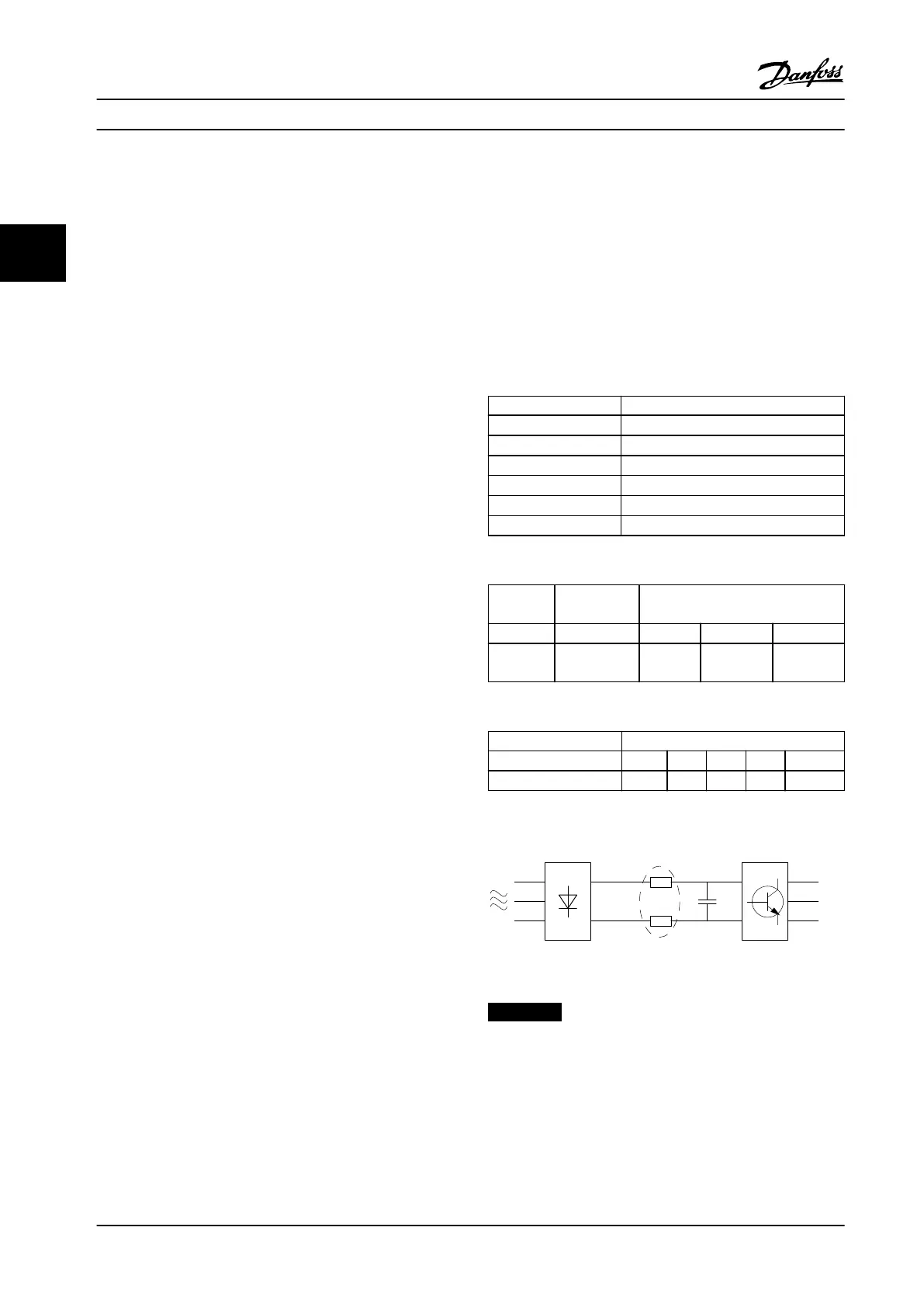
Figure 3.3 Intermediate Circuit Coils
NOTICE!
Some of the harmonic currents can disturb communi-
cation equipment connected to the same transformer or
cause resonance in connection with power-factor
correction capacitors.
To ensure low harmonic currents, the adjustable frequency
drive is equipped with passive lters. DC coils reduce the
total harmonic distortion (THD) to 40%.
System Integration
VLT
®
AQUA Drive FC 202
50 Danfoss A/S © 09/2014 All rights reserved. MG20N622
33

 Loading...


