7.9 dU/dt Testing
To avoid damage to motors without phase insulation paper
or other insulation reinforcement designed for operation of
the adjustable frequency drive, installation of a dU/dt lter
or LC lter on the output of the adjustable frequency drive
is recommended.
When a transistor in the inverter bridge switches, the
voltage across the motor increases by a dU/dt ratio
depending on:
•
Motor inductance
•
Motor cable (type, cross-section, length, shielded,
or non-shielded)
The natural induction causes an overshoot voltage peak in
the motor voltage before it stabilizes. The level depends
on the voltage in the DC link.
Peak voltage on the motor terminals is caused by the
switching of the IGBTs. The rise time and the peak voltage
aects the service life of the motor. If the peak voltage is
too high, motors without phase coil insulation can be
adversely aected over time.
With short motor cables (several feet or meters), the rise
time and peak voltage are lower. The rise time and peak
voltage increase with cable length.
The adjustable frequency drive complies with IEC 60034-25
and IEC 60034-17 for motor design.
7.9.1
Peak Voltage on Motor
To obtain approximate values for cable lengths and
voltages not mentioned below, use the following “Rules of
Thumb”:
1. Rise time increases/decreases proportionally with
cable length.
2. U
PEAK
= DC link voltage x 1.9
(DC link voltage = AC line voltage x 1.35).
3.
dU/dt =
0 . 8 × U
PEAK
Rise time
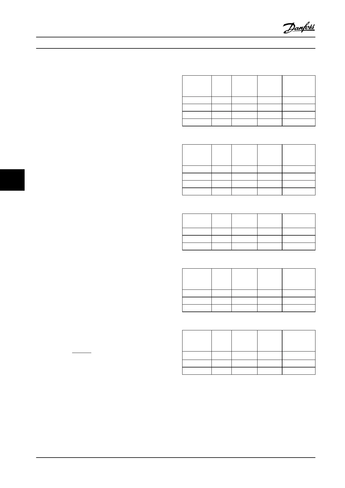
Data is measured according to IEC 60034-17.
Cable lengths are in meters.
200–240 V (T2)
Cable
length [m]
AC line
voltage
[V]
Rise time
[μsec]
U
PEAK
[kV]
dU/dt
[kV/μsec]
36 240 0.226 0.616 2.142
50 240 0.262 0.626 1.908
100 240 0.650 0.614 0.757
150 240 0.745 0.612 0.655
Table 7.32 Adjustable Frequency Drive, P5K5, T2
Cable
length [m]
AC line
voltage
[V]
Rise time
[μsec]
U
PEAK
[kV]
dU/dt
[kV/μsec]
5 230 0.13 0.510 3.090
50 230 0.23 0.590 2.034
100 230 0.54 0.580 0.865
150 230 0.66 0.560 0.674
Table 7.33 Adjustable Frequency Drive, P7K5, T2
Cable
length [m]
Rise time
[μsec]
U
PEAK
[kV]
dU/dt
[kV/μsec]
36 240 0.264 0.624 1.894
136 240 0.536 0.596 0.896
150 240 0.568 0.568 0.806
Table 7.34 Adjustable Frequency Drive, P11K, T2
Cable
length [m]
AC line
voltage
[V]
Rise time
[μsec]
U
PEAK
[kV]
dU/dt
[kV/μsec]
30 240 0.556 0.650 0.935
100 240 0.592 0.594 0.807
150 240 0.708 0.575 0.669
Table 7.35 Adjustable Frequency Drive, P15K, T2
Cable
length [m]
AC line
voltage
[V]
Rise time
[μsec]
U
PEAK
[kV]
dU/dt
[kV/μsec]
36 240 0.244 0.608 1.993
136 240 0.568 0.580 0.832
150 240 0.720 0.574 0.661
Table 7.36 Adjustable Frequency Drive, P18K, T2
Specications
VLT
®
AQUA Drive FC 202
182 Danfoss A/S © 09/2014 All rights reserved. MG20N622
77

 Loading...


