130BP066.10
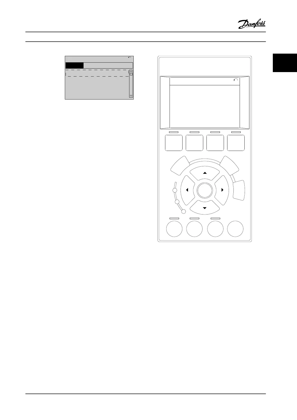
1107 RPM
0 - ** Operation/Display
1 - ** Load/Motor
2 - ** Brakes
3 - ** Reference / Ramps
3.84 A 1 (1)
Main Menu
Figure 2.23 Sample Programming Menu
Local user interface
For local programming, parameters are accessible by
pressing either [Quick Menu] or [Main Menu] on the LCP.
The Quick Menu is intended for initial start up and motor
characteristics. The Main Menu accesses all parameters and
allows for advanced applications programming.
Remote user interface
For remote programming, Danfoss oers a software
program for developing, storing, and transferring
programming information. MCT 10 Set-up Software allows
the user to connect a PC to the adjustable frequency drive
and perform live programming rather than using the LCP
keypad. Or programming can be done oine and simply
downloaded to the unit. The entire drive prole can be
loaded onto the PC for backup storage or analysis. A USB
connector and RS485 terminal are available for connecting
to the adjustable frequency drive.
MCT 10 Set-up Software is available for free download at
www.VLT-software.com. A CD is also available by requesting
part number 130B1000. A user’s manual provides detailed
operation instructions. See also chapter 2.8.2 PC Software.
Programming control terminals
•
Each control terminal has specied functions it is
capable of performing.
•
Parameters associated with the terminal enable
the function selections.
•
For proper drive functioning using control
terminals, the terminals must be:
-
Wired properly.
-
Programmed for the intended function.
2.8.1
Local Control Panel
The local control panel (LCP) is a graphic display on the
front of the unit, which provides the user interface through
push-button controls and displays status messages,
warnings and alarms, programming parameters, and more.
A numeric display is also available with limited display
options. Figure 2.24 shows the LCP.
Auto
on
Reset
Hand
on
Off
Status
Quick
Menu
Main
Menu
Alarm
Log
Back
Cancel
Info
OK
Status
1(1)
1234rpm 10,4A 43,5Hz
Run OK
43,5Hz
On
Alarm
Warn.
130BB465.10
a
b
c
d
Figure 2.24 Local Control Panel
2.8.2
PC Software
The PC is connected via a standard (host/device) USB
cable, or via the RS485 interface.
USB is a serial bus utilizing four shielded wires with
Ground pin 4 connected to the shield in the PC USB port.
When connecting the PC to an adjustable frequency drive
through the USB cable, there is a potential risk of
damaging the PC USB host controller. All standard PCs are
manufactured without galvanic isolation in the USB port.
Any ground potential dierence caused by not following
the recommendations described in the instruction manual,
can damage the USB host controller through the shield of
the USB cable.
It is recommended to use a USB isolator with galvanic
isolation to protect the PC USB host controller from
ground potential
dierences when connecting the PC to
an adjustable frequency drive through a USB cable.
Product Overview
Design Guide
MG20N622 Danfoss A/S © 09/2014 All rights reserved. 35
2 2

 Loading...


