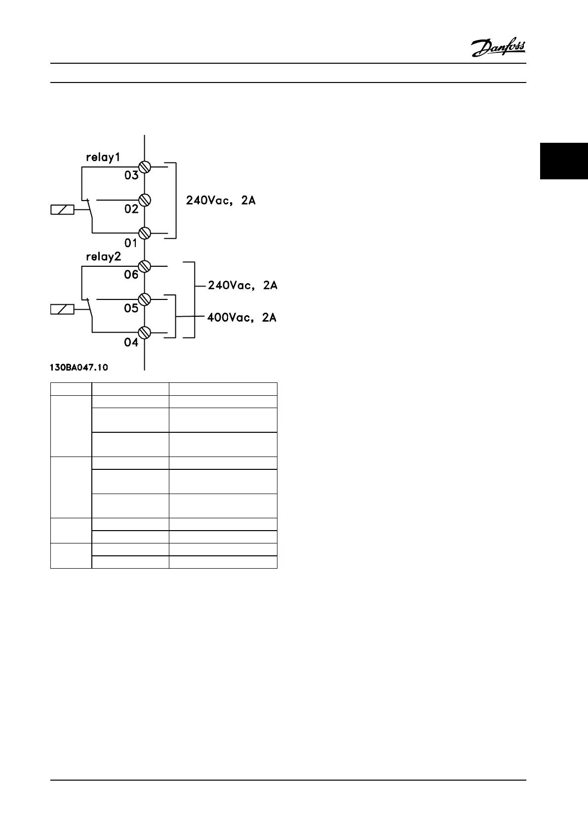
3.5.2 Relay Connections
Relay
Terminal
1)
Description
1 1 common
2 normally open
maximum 240 V
3 normally closed
maximum 240 V
2 4 common
5 normally closed
maximum 240 V
6 normally closed
maximum 240 V
1 01-02 make (normally open)
01-03 break (normally closed)
2 04-05 make (normally open)
04-06 break (normally closed)
Figure 3.21 Relay Outputs 1 and 2, Maximum Voltages
1) To add more relay outputs, install VLT
®
Relay Option
Module MCB 105 or VLT
®
Relay Option Module MCB 113.
For more information about relays, refer to
chapter 7
Specications and chapter 8.3 Relay Terminal
Drawings.
For more information about relay options, refer to
chapter 3.7 Options and Accessories.
System Integration
Design Guide
MG20N622 Danfoss A/S © 09/2014 All rights reserved. 65
3 3

 Loading...


