3.5 Additional Inputs and Outputs
3.5.1 Wiring Schematic
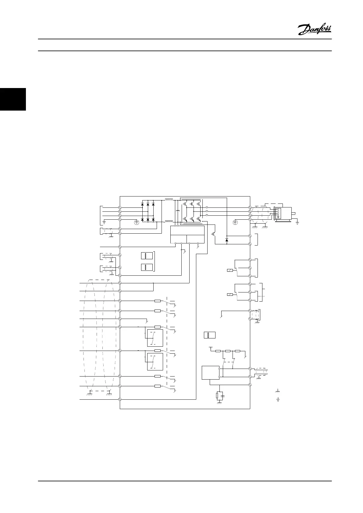
When wired and properly programmed, the control terminals provide:
•
Feedback, reference, and other input signals to the adjustable frequency drive.
•
Output status and fault conditions from the adjustable frequency drive.
•
Relays to operate auxiliary equipment.
•
A serial communication interface.
•
24 V common.
Control terminals are programmable for various functions by selecting parameter options through the local control panel
(LCP) on the front of the unit or external sources. Most control wiring is customer-supplied, unless specied in the factory
order.
+ - + -
S202
**
*
Motor
Analog Output
relay1
relay2
ON=Terminated
OFF=Open
50 (+10 V OUT)
53 (A IN)
54 (A IN)
55 (COM A IN)
12 (+24 V OUT)
13 (+24 V OUT)
37 (D IN)
18 (D IN)
(COM D IN)
(COM A OUT) 39
(A OUT) 42
(P RS-485) 68
(N RS-485) 69
(COM RS-485) 61
0/4–20 mA
240 V AC, 2 A
24 V (NPN)
0 V (PNP)
0 V (PNP)
24 V (NPN)
19 (D IN)
24 V (NPN)
0 V (PNP)
(D IN/OUT)
0 V (PNP)
24 V (NPN)
(D IN/OUT)
24 V (NPN)
0 V (PNP)
0 V (PNP)
24 V (NPN)
33 (D IN)
32 (D IN)
: Chassis
: Ground
240 V AC, 2 A
400 V AC, 2 A
91 (L1)
92 (L2)
93 (L3)
PE
88 (-)
89 (+)
20
10 V DC
15 mA 130/200 mA
(U) 96
(V) 97
(W) 98
(PE) 99
0 V
5 V
S801
RS-485
03
24 V DC
02
01
05
04
06
27
24 V
0 V
0 V
24 V
29
1 2
ON
S201
ON
21
ON=0/4–20 mA
OFF=0/-10 V DC -
+10 V DC
95
P 5-00
21
ON
S801
(R+) 82
(R-) 81
130BD552.10
3-phase
power
input
DC bus
+10 V DC
0/-10 V DC-
+10 V DC
0/4–20 mA
0/-10 V DC-
+10 V DC
0/4–20 mA
Switch Mode
Power Supply
Brake
resistor
RS-485
Interface
Figure 3.20 Basic Wiring Schematic
A=Analog, D=Digital
*Terminal 37 (optional) is used for STO. For STO installation instructions, refer to the VLT
®
Safe Torque O Instruction Manual.
**Do not connect cable shield.
System Integration
VLT
®
AQUA Drive FC 202
64 Danfoss A/S © 09/2014 All rights reserved. MG20N622
33

 Loading...


