1
2
z
z
z
L1
L2
L3
PE
U
V
W
C
S
I
2
I
1
I
3
I
4
C
S
C
S
C
S
C
S
I
4
C
S
z
PE
3
4
5
6
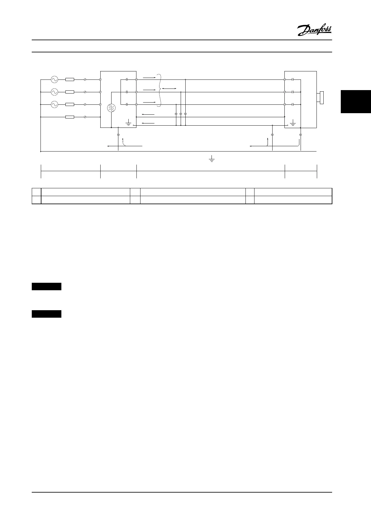
1 Ground wire 3 AC line power supply 5 Shielded motor cable
2 Shield 4 Adjustable frequency drive 6 Motor
Figure 3.2 Generation of Leakage Currents
3.2.2
EMC Test Results
The following test results have been obtained using a system with an adjustable frequency drive, a shielded control cable, a
control box with potentiometer, as well as a single motor and shielded motor cable (Ölex Classic 100 CY) at nominal
switching frequency. Table 3.4 states the maximum motor cable lengths for compliance.
NOTICE!
Conditions may change signicantly for other set-ups.
NOTICE!
Consult Table 3.17 for parallel motor cables.
System Integration Design Guide
MG20N622 Danfoss A/S © 09/2014 All rights reserved. 45
3 3

 Loading...


