Parameters
FC
+24 V
+24 V
D IN
D IN
D IN
COM
D IN
D IN
D IN
D IN
+10
A IN
A IN
COM
A OUT
COM
R1R2
12
13
18
19
20
27
29
32
33
37
50
53
54
55
42
39
01
02
03
04
05
06
130BB684.10
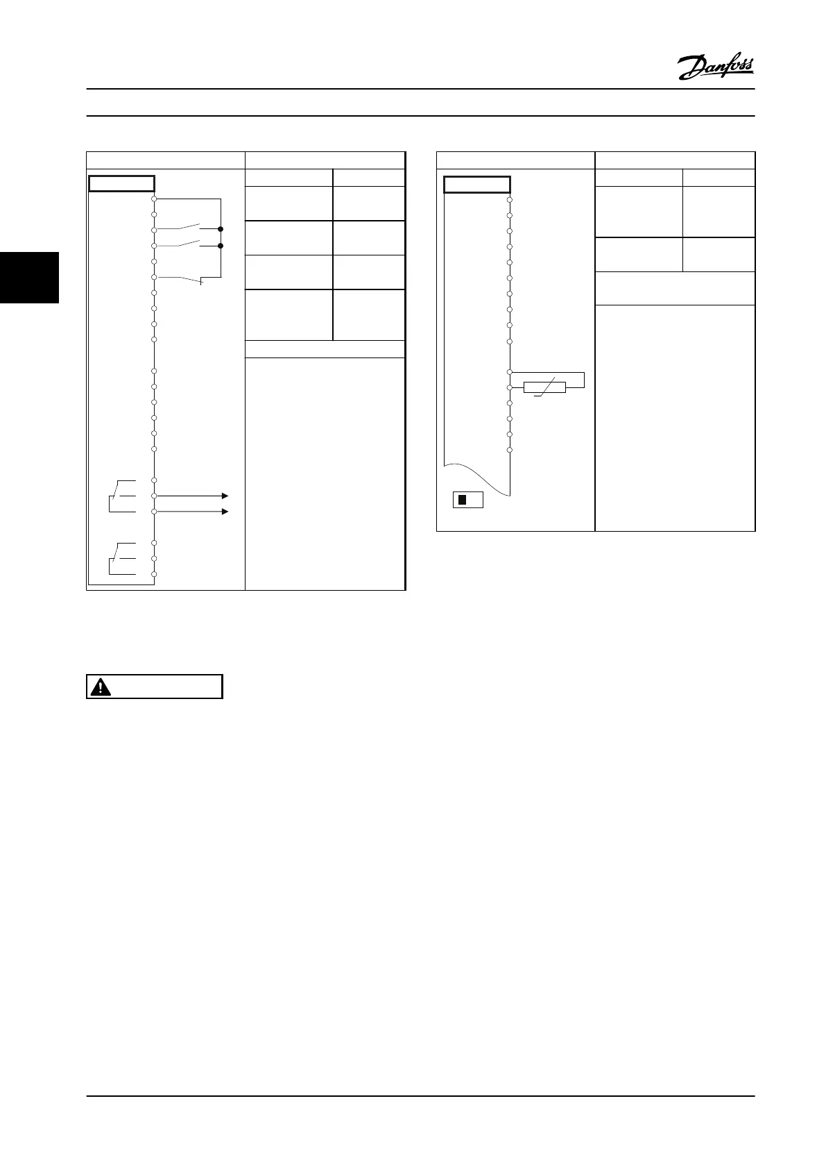
Function Setting
5-10 Terminal 18
Digital Input
[8] Start*
5-11 Terminal 19
Digital Input
[52] Run
Permissive
5-12 Terminal 27
Digital Input
[7] External
interlock
5-40 Function
Relay
[167] Start
command
act.
* = Default value
Notes/comments:
D IN 37 is an option.
Table 4.15 Run Permissive
4.3.12
Motor Thermistor
WARNING
THERMISTOR INSULATION
Risk of personal injury or equipment damage.
•
Use only thermistors with reinforced or double
insulation to meet PELV insulation
requirements.
Parameters
130BB686.12
VLT
+24 V
+24 V
D IN
D IN
D IN
COM
D IN
D IN
D IN
+10 V
A IN
A IN
COM
A OUT
COM
12
13
18
19
20
27
29
32
33
50
53
54
55
42
39
A53
U - I
D IN
37
Function Setting
1-90 Motor
Thermal
Protection
[2]
Thermistor
trip
1-93 Thermistor
Source
[1] Analog
input 53
* = Default Value
Notes/comments:
If only a warning is desired,
parameter 1-90 Motor Thermal
Protection should be set to [1]
Thermistor warning.
D IN 37 is an option.
Table 4.16 Motor Thermistor
Application Examples
VLT
®
AQUA Drive FC 202
114 Danfoss A/S © 09/2014 All rights reserved. MG20N622
44

 Loading...


