3.8.11.2 Storage of Data
The coil 65 decimal determines whether data written to
the adjustable frequency drive is stored in EEPROM and
RAM (coil 65=1) or only in RAM (coil 65=0).
3.8.11.3 IND (Index)
Some parameters in the adjustable frequency drive are
array parameters, for example, 3-10 Preset Reference. Since
the Modbus does not support arrays in the holding
registers, the adjustable frequency drive has reserved the
holding register 9 as pointer to the array. Before reading or
writing an array parameter, set the holding register 9.
Setting the holding register to the value of 2 causes all
following read/write to array parameters to be to the index
2.
3.8.11.4
Text Blocks
Parameters stored as text strings are accessed in the same
way as the other parameters. The maximum text block size
is 20 characters. If a read request for a parameter is for
more characters than the parameter stores, the response is
truncated. If the read request for a parameter is for fewer
characters than the parameter stores, the response is
padded with spaces.
3.8.11.5
Conversion Factor
Since a parameter value can only be transferred as a whole
number, a conversion factor must be used to transfer
decimals.
3.8.11.6
Parameter Values
Standard data types
Standard data types are int 16, int 32, uint 8, uint 16 and
uint 32. They are stored as 4x registers (40001–4FFFF). The
parameters are read using function 03 hex Read Holding
Registers. Parameters are written using the function 6 hex
Preset Single Register for 1 register (16 bits), and the
function 10 hex Preset Multiple Registers for two registers
(32 bits). Readable sizes range from one register (16 bits)
up to ten registers (20 characters).
Non-standard data types
Non-standard data types are text strings and are stored as
4x registers (40001–4FFFF). The parameters are read using
function 03 hex Read Holding Registers and written using
function 10 hex Preset Multiple Registers. Readable sizes
range from one register (two characters) up to ten registers
(20 characters).
3.8.12
FC Drive Control Prole
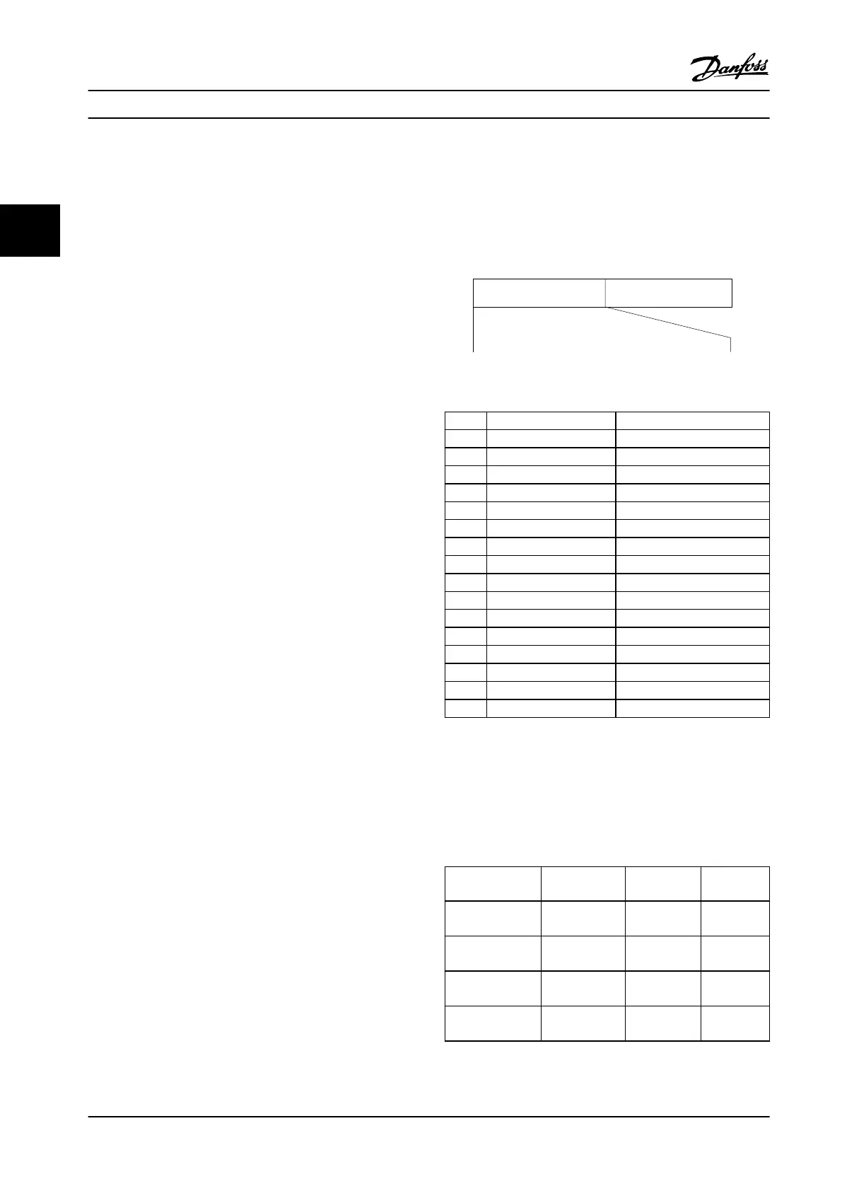
3.8.12.1 Control Word According to FC
Prole (8-10 Control Prole=FC
prole)
Speed ref.CTW
Master-follower
130BA274.11
15 14 13 12 11 10 9 8 7 6 5 4 3 2 1 0
Bit
no.:
Figure 3.56 Control Word
Bit Bit value=0 Bit value=1
00 Reference value External selection lsb
01 Reference value External selection msb
02 DC brake Ramp
03 Coasting No coasting
04 Quick stop Ramp
05 Hold output frequency Use ramp
06 Ramp stop Start
07 No function Reset
08 No function Jog
09 Ramp 1 Ramp 2
10 Data invalid Data valid
11 No function Relay 01 active
12 No function Relay 02 active
13 Parameter set-up Selection lsb
14 Parameter set-up Selection msb
15 No function Reverse
Table 3.43 Control Word Bits
Explanation of the Control Bits
Bits 00/01
Bits 00 and 01 are used to select between the four
reference values, which are pre-programmed in 3-10 Preset
Reference according to Table 3.44.
Programmed ref.
value
Parameter Bit 01 Bit 00
1
3-10 Preset
Reference [0]
0 0
2
3-10 Preset
Reference [1]
0 1
3
3-10 Preset
Reference [2]
1 0
4
3-10 Preset
Reference [3]
1 1
Table 3.44 Reference Values
System Integration
VLT
®
AQUA Drive FC 202
92 Danfoss A/S © 09/2014 All rights reserved. MG20N622
33

 Loading...


