•
Basic cascade control: Speed control of a single
pump in a multi-pump system. This is a cost-
attractive solution in, for example, booster sets.
•
Master-follower: Control up to eight adjustable
frequency drives and pumps to ensure smooth
operation of the overall pump system.
4.2.2 Quick Menu Water and Pumps
The quick menu entry water and pumps provides quick
access to the most common water and pump features of
the VLT
®
AQUA Drive:
•
Special ramps
(initial/nal ramp, check valve
ramp)
•
Sleep mode
•
Deragging
•
Dry-run detection
•
End of curve detection
•
Flow compensation
•
Pipe ll mode for horizontal, vertical and mixed
pipe systems
•
Control performance
•
Minimum speed monitor
4.2.3
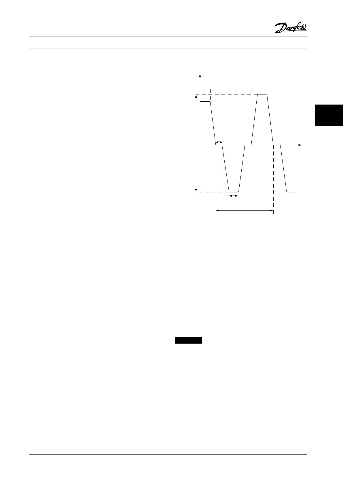
29-1* Deragging Function
The purpose of the deragging feature is to free the pump
blade of debris in waste water applications so that the
pump operates normally.
A deragging event is dened as the time when the
adjustable frequency drive starts to derag to when the
deragging nishes. When a derag is started, the adjustable
frequency drive ramps rst to a stop and then an o delay
expires before the rst cycle begins.
0 Hz / RPM
Derag O Delay:
Par. 29 -15
+/- Derag
Speed:
Par.: 29 -13
Par.: 29 -14
Deragging Run Time : Par . 29-12
Speed
Derag
function
activated
1 Cycle
Number of Cycles : Par . 29 -10
130BC369.10
Figure 4.1 Derag Function
If a derag is triggered from an adjustable frequency drive-
stopped state, the rst o delay is skipped. The deragging
event may consist of several cycles. One cycle consisting of
one pulse in the reverse direction followed by one pulse in
the forward direction. Deragging is considered nished
after the specied number of cycles has completed. More
specically, on the last pulse (it will always be forward) of
the last cycle, the derag is considered nished after the
deragging run time expires (the adjustable frequency drive
is running at derag speed). In between pulses, the
adjustable frequency drive output coasts for a specied o
delay time to let debris in the pump settle.
NOTICE!
Do not enable deragging if the pump cannot operate in
reverse direction.
There are three dierent notications for an ongoing
deragging event:
•
Status in the LCP: Auto Remote Derag.
•
A bit in the extended status word (Bit 23, 80 0000
hex).
•
A digital output can be congured to reect the
active deragging status.
Application Examples
Design Guide
MG20N622 Danfoss A/S © 09/2014 All rights reserved. 101
4 4

 Loading...


