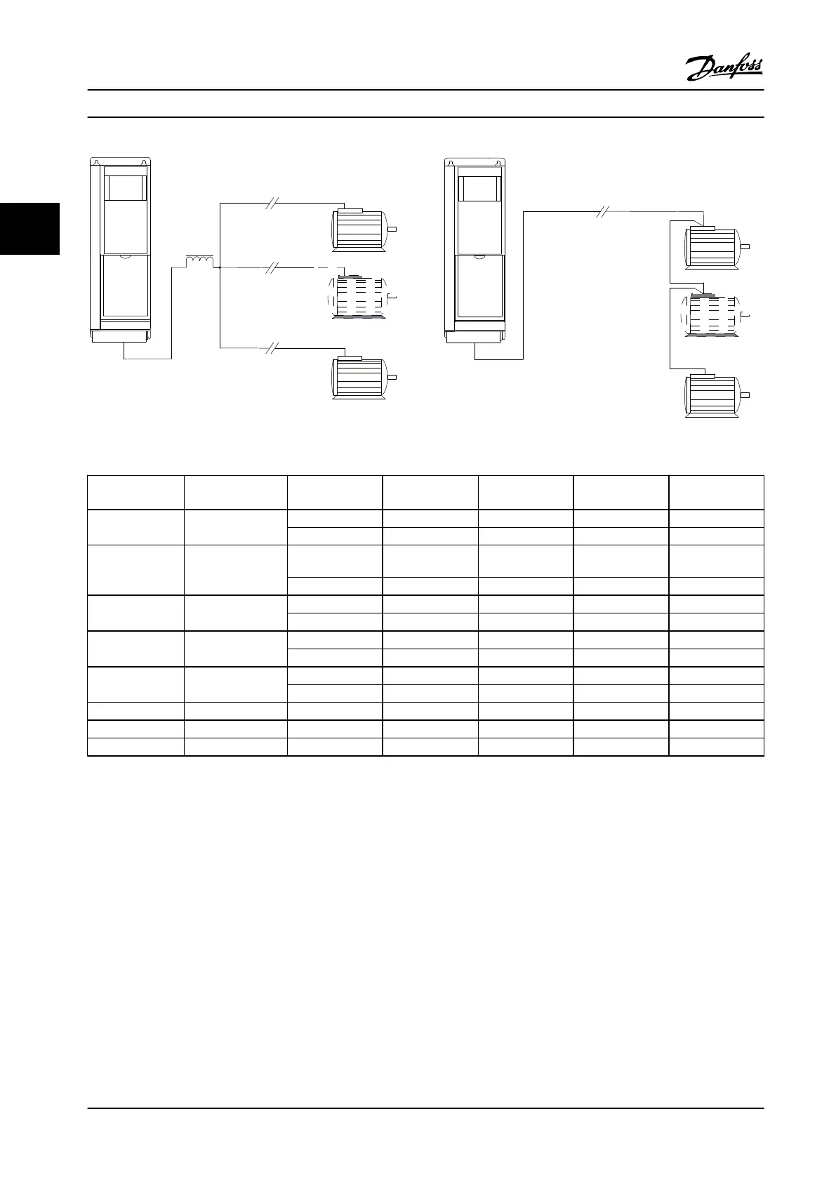
Figure 3.15 LC Filter for Long Parallel Cables
Figure 3.16 Long Cables in Series Connection
Enclosure sizes Power Size [kW
(hp)]
Voltage [V] 1 cable [m (ft)] 2 cables [m (ft)] 3 cables [m (ft)] 4 cables [m (ft)]
A1, A2, A4, A5 0.37–0.75 (0.5–1)
400 150 (500) 45 (148) 8 (26.3) 6 (20)
500 150 (500) 7 (23) 4 (13) 3 (10)
A2, A4, A5 1.1–1.5 (1.5–2)
400 150 (500) 45 (148) 20 (66) 8 (26.3)
500 150 (500) 45 (148) 5 (16.4) 4 (13)
A2, A4, A5 2.2–4 (3–5)
400 150 (500) 45 (148) 20 (66) 11 (36)
500 150 (500) 45 (148) 20 (66) 6 (20)
A3, A4, A5 5.5–7.5 (7.5–10)
400 150 (500) 45 (148) 20 (66) 11 (36)
500 150 (500) 45 (148) 20 (66) 11 (36)
B1, B2, B3, B4,
C1, C2, C3, C4
11–90 (15–125)
400 150 (500) 75 (250) 50 (164) 37 (123)
500 150 (500) 75 (250) 50 (164) 37 (123)
A3 1.1–7.5 (1.5–10) 525–690 100 (330) 50 (164) 33 (108.3) 25 (82)
B4 11–30 (15–40) 525–690 150 (500) 75 (250) 50 (164) 37 (123)
C3 37–45 (50–60) 525–690 150 (500) 75 (250) 50 (164) 37 (123)
Table 3.17 Maximum Cable Length for Each Parallel Cable
3.4.7
Control Wire Isolation
Harmonic interference generated by motor cabling can
degrade control signals in the drive control wiring and
result in control faults. Motor cables and control wiring
should be separate. Interference eects decrease signi-
cantly with separation.
•
The distance between control wiring and motor
cables should be more than 200 mm (11.8 in).
•
Divider strips are essential with smaller
separations or interference may be coupled in or
transferred.
•
Control cable shields must be connected at both
ends in the same way as motor cable shields.
•
Shielded cables with twisted conductors provide
highest attenuation. The attenuation of the
magnetic eld increases from around 30 dB with
a single shield to 60 dB with a double shield and
to approximately 75 dB if the conductors are also
twisted.
System Integration
VLT
®
AQUA Drive FC 202
60 Danfoss A/S © 09/2014 All rights reserved. MG20N622
33

 Loading...


