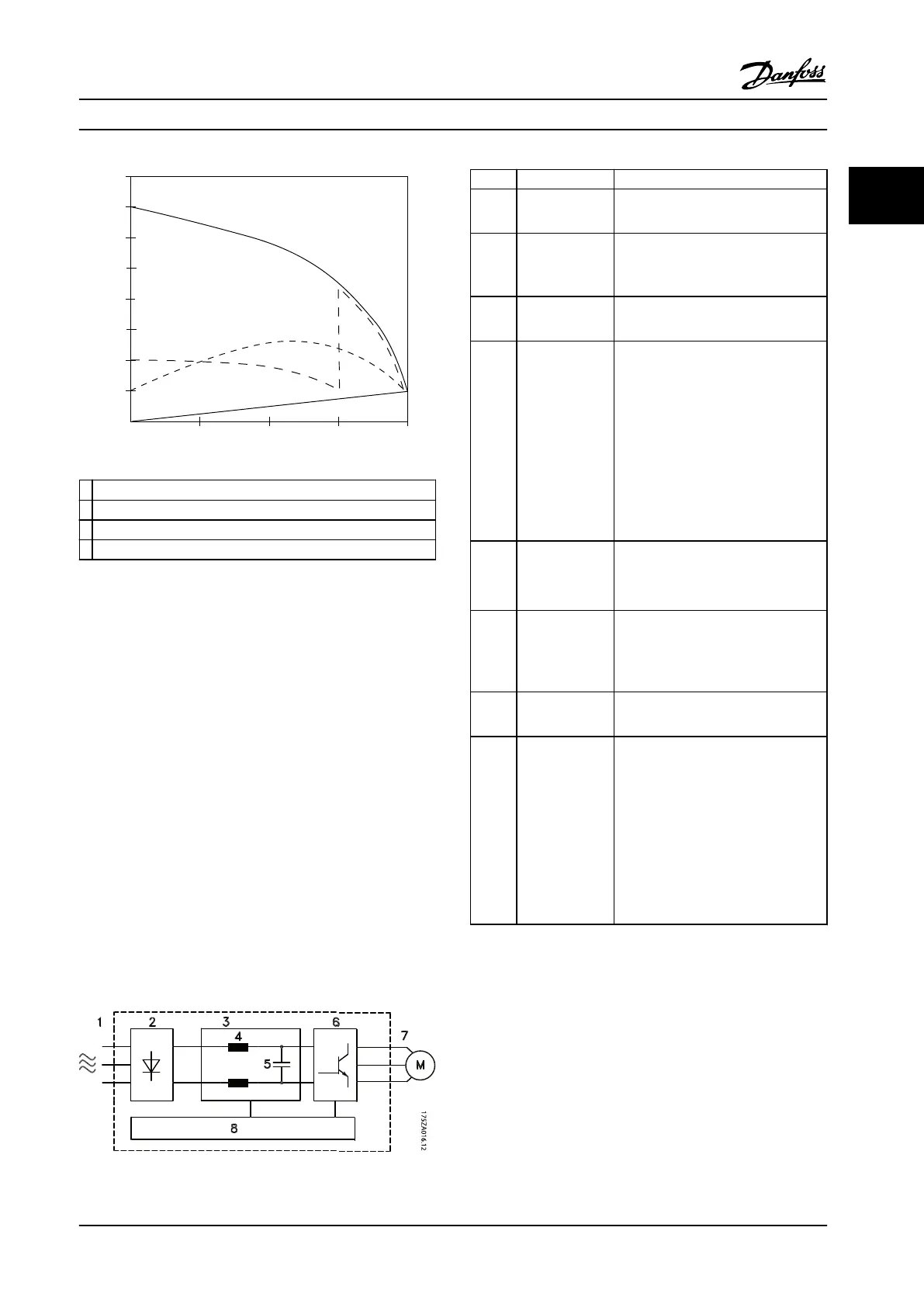
Full load
% Full load current
& speed
500
100
0
0 12,5 25 37,5 50Hz
200
300
400
600
700
800
4
3
2
1
175HA227.10
1
VLT
®
AQUA Drive FC 202
2 Star/delta starter
3 Soft starter
4 Start directly on line power
Figure 2.8 Start-up Current
2.2
Description of Operation
The adjustable frequency drive supplies a regulated
amount of AC line power to the motor to control its speed.
The adjustable frequency drive supplies variable frequency
and voltage to the motor.
The adjustable frequency drive is divided into four main
modules:
•
Rectier
•
Intermediate DC bus circuit
•
Inverter
•
Control and regulation
Figure 2.9 is a block diagram of the internal components of
the adjustable frequency drive. See Table 2.3 for their
functions.
Figure 2.9 Adjustable Frequency Drive Block Diagram
Area Title Functions
1
Line power
input
•
3-phase AC line power supply to
the adjustable frequency drive.
2 Rectier
•
The rectier bridge converts the
AC input to DC current to supply
inverter power.
3 DC bus
•
Intermediate DC bus circuit
handles the DC current.
4 DC reactors
•
Filter the intermediate DC circuit
voltage.
•
Prove electrical transient
protection.
•
Reduce RMS current.
•
Raise the power factor reected
back to the line.
•
Reduce harmonics on the AC
input.
5 Capacitor bank
•
Stores the DC power.
•
Provides ride-through protection
for short power losses.
6 Inverter
•
Converts the DC into a controlled
PWM AC waveform for a
controlled variable output to the
motor.
7 Output to motor
•
Regulated 3-phase output power
to the motor.
8 Control circuitry
•
Input power, internal processing,
output, and motor current are
monitored to provide ecient
operation and control.
•
User interface and external
commands are monitored and
performed.
•
Status output and control can be
provided.
Table 2.3 Legend to Figure 2.9
1. The adjustable frequency drive
recties AC
voltage from line power into DC voltage.
2. The DC voltage is converted into an AC current
with a variable amplitude and frequency.
The adjustable frequency drive supplies the motor with
variable voltage/current and frequency, which enables
variable speed control of 3-phased, standard asynchronous
motors and non-salient PM motors.
Product Overview
Design Guide
MG20N622 Danfoss A/S © 09/2014 All rights reserved. 19
2 2

 Loading...


